Digital Frequency
Display for Heathkit SB, HW, HR Series
Also For the Kenwood TS-520(S / SE)

1. Introduction
I
replicated the AADE
custom DFD-2 for the Heathkit SB line, for the HW radios, for the
solid state HR-1680, for the Kenwood TS-520S, and for the Drake 2
series. This project
has been designed for the experienced homebrewer.
Bare-bones boards and pre-programmed PIC
processors
are available for
others who might like to build one (firmware not available).
I will not have the
time
to coach anyone through the building process nor assist with the
installation within any particular radio. For this, you
should
probably refer Neil's website on the Wayback Machine.
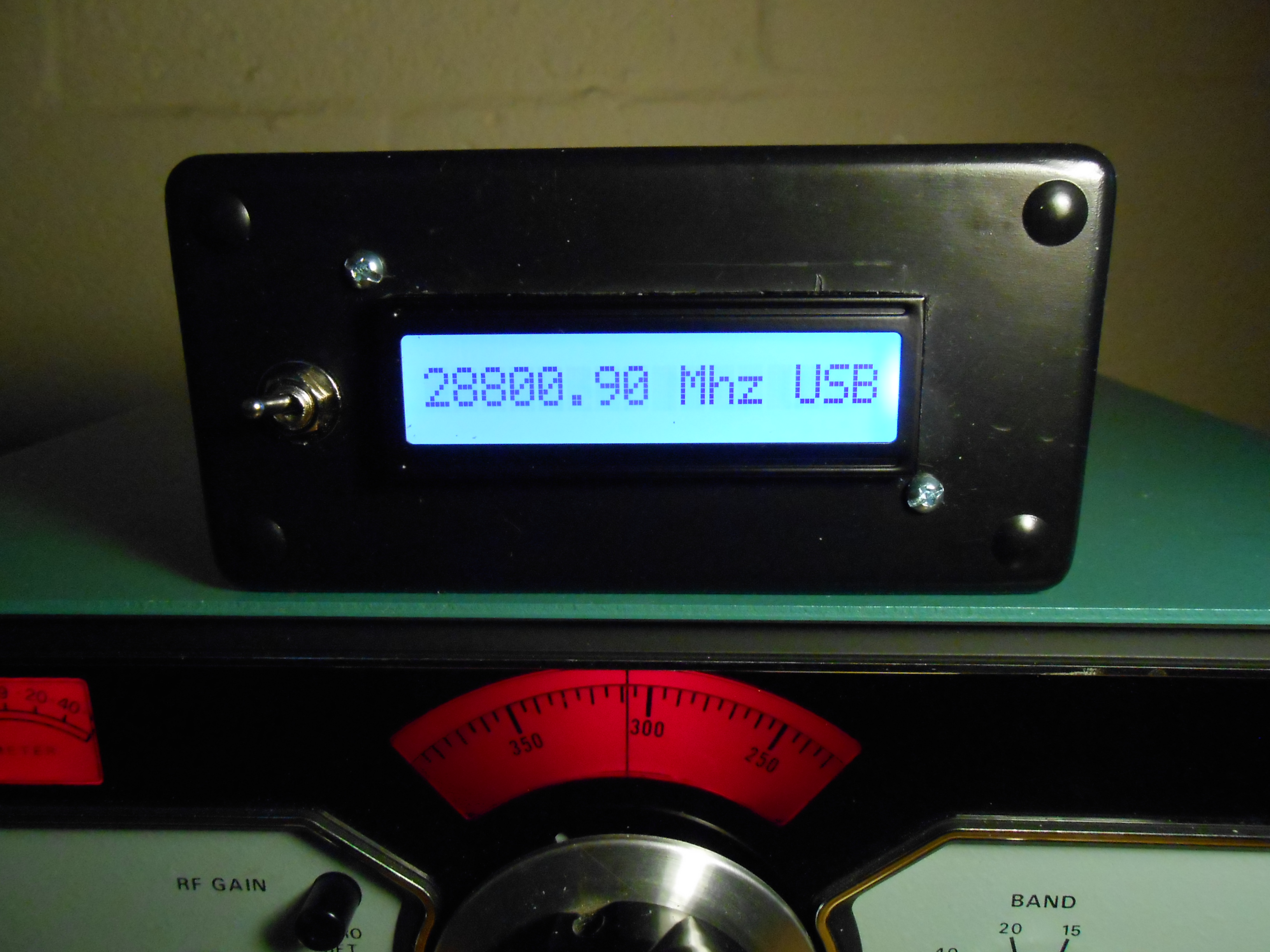
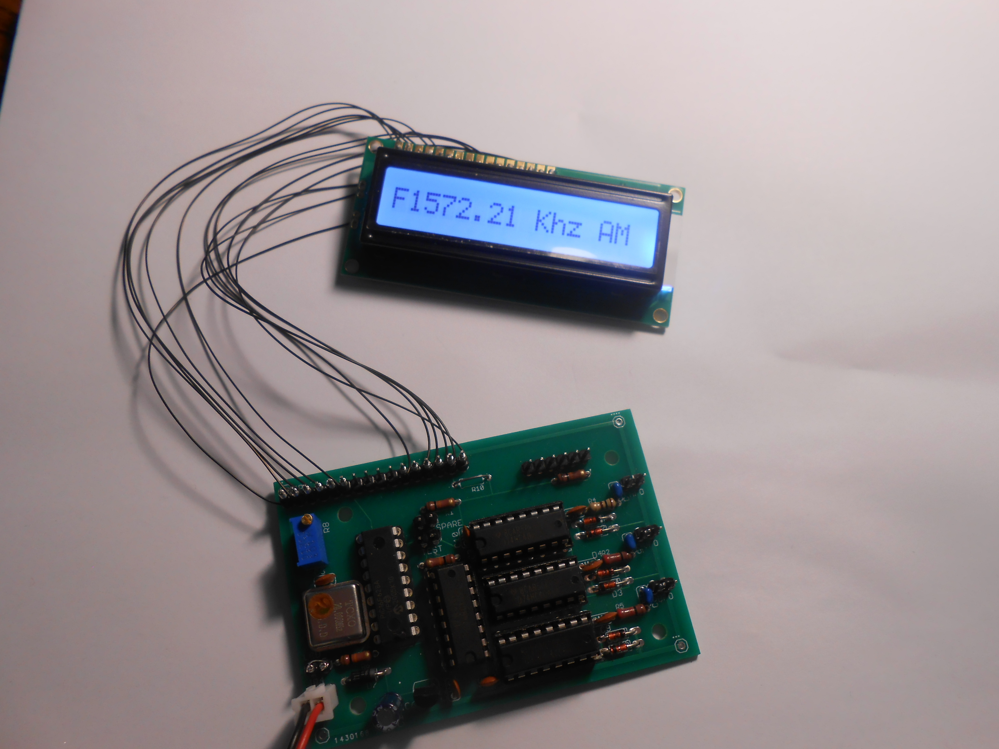
You'll notice in the picture that this particular display has been
installed in a very large enclosure, mainly because I wanted to use a
large, 1x16, one line display. Since the P/C
board itself is just
2.by 3 inches, it may be readily mounted in a smaller enclosure
(providing a smaller LCD
is used). The LCD itself can be 'wired'
to plug directly into the P/C board, or connected to the board by
either a ribbon cable or individual 30 gauge wires - your choice!
Important Note: Software purchased after 10/20/2021 will have the changes shown in red. The PCB itself may be upgraded later.
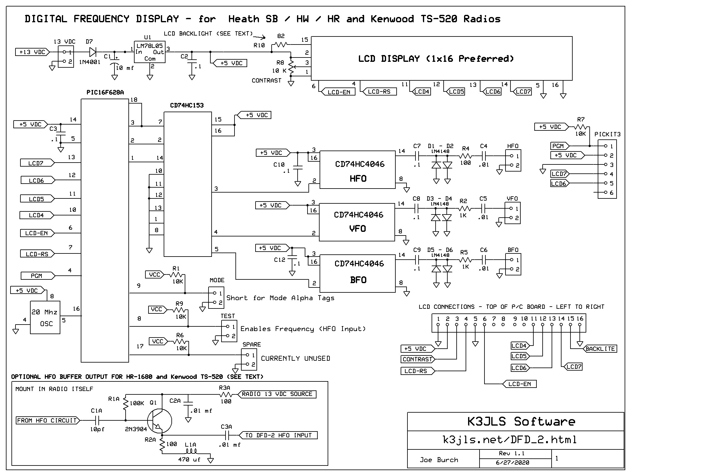
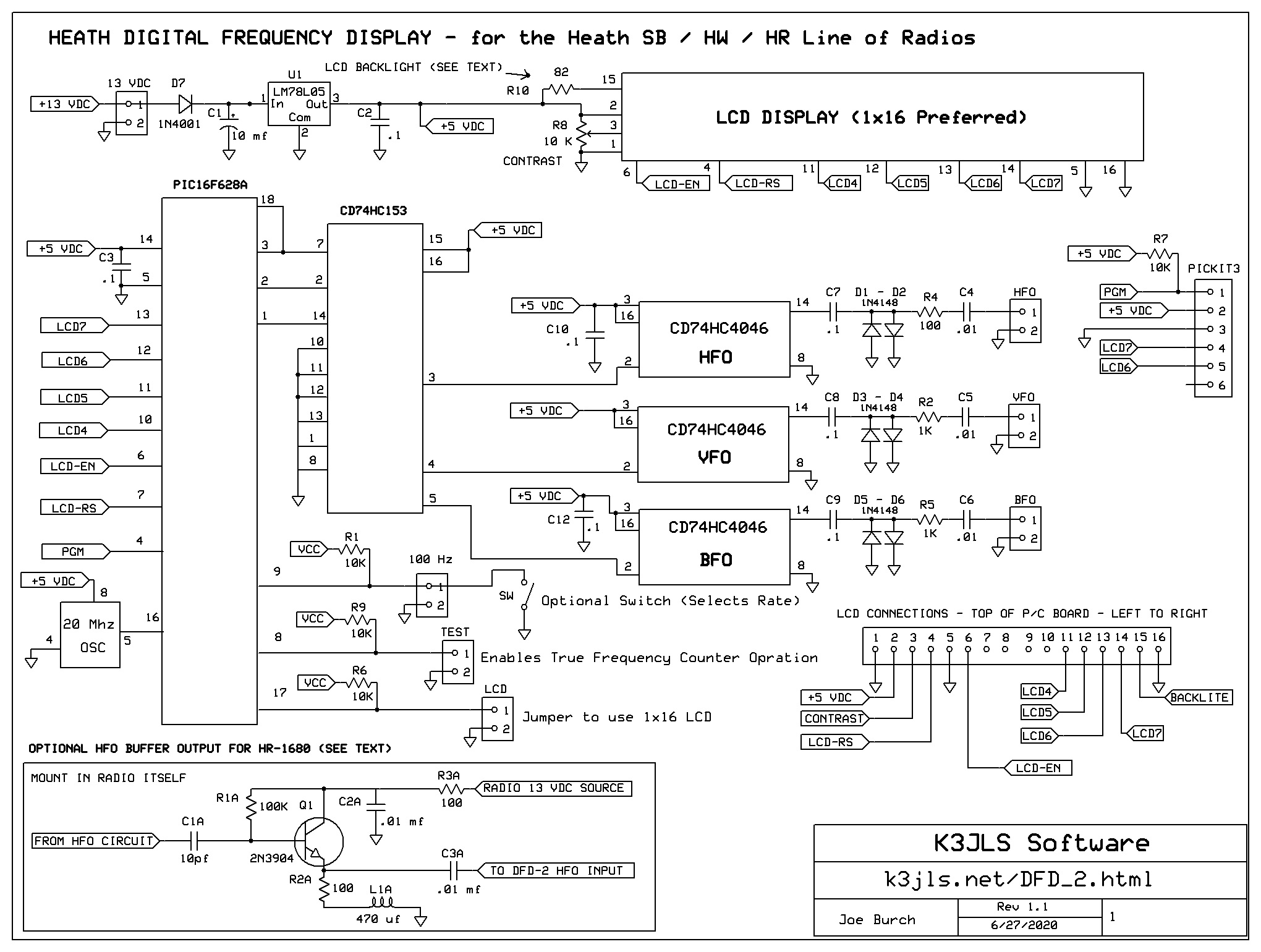
2.
Design
and Schematic -
Phase 3 Board (Current)
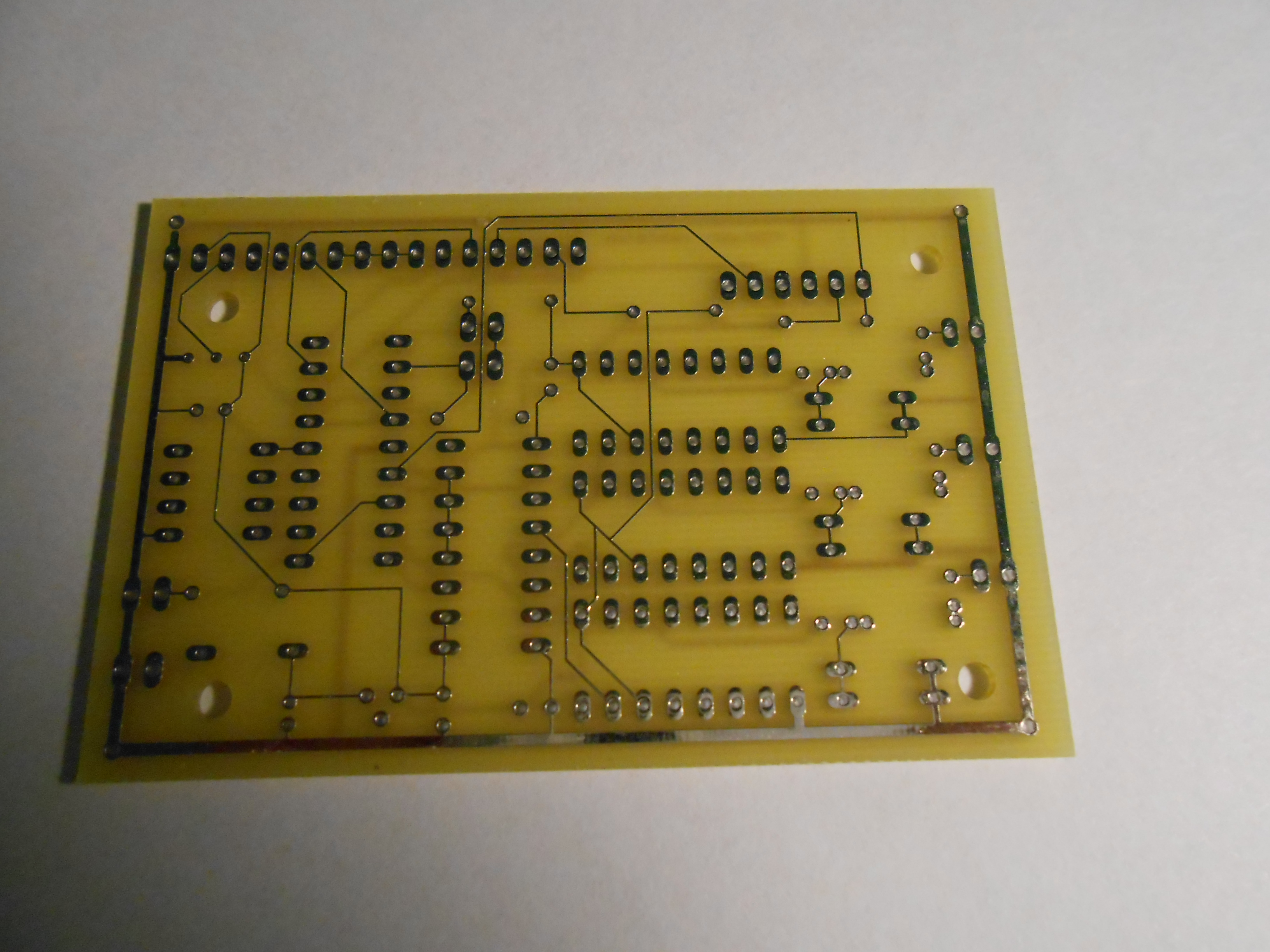
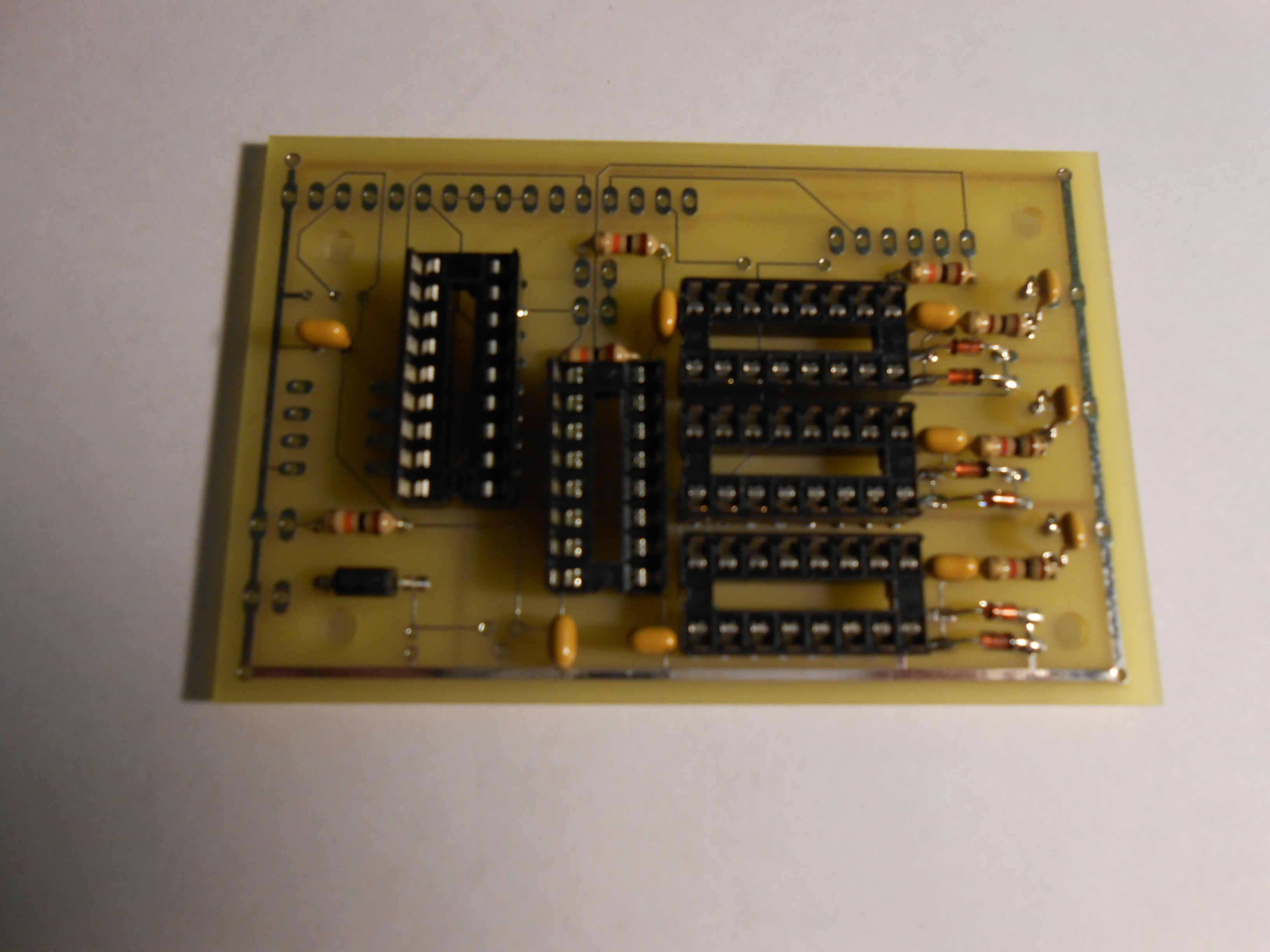
P/C board design:
- the
board
itself
is 2" by 3",
- either a 'canned' oscillator or a mechanically trimmed TCXO
can be used, the
- chassis
mounting holes have been provided should the user desire to mount the
unit against the chassis and wire the display separately.
3.
How It Works - This program
will check the
frequency and provide a standard 100 Hz
readout. The LCD is updated only when the
frequency changes, thus eliminating the annoying 'chirps'
when the frequency has not changed.
4. Construction
Details (read on down)
Note: if you are
building this board, you
first have to determine if you want
to mount the LCD display directly to the P/C board, or just mount the
P/C board on the chassis and then use either 30 gauge wire or ribbon
cable to interconnect the
two. You also have to decide upon a suitable enclosure if the
display is to be mounted externally. If you plan to mount
the LCD on the P/C board, then the TEST
and SPARE
two
wire pins must be mounted on the foil side of the board along with R8
(the LCD contrast adjustment).
Note: When
populating the P/C board, it's vital that the components be installed
on the proper (silkscreened) side. Removing incorrectly placed
components can be difficult, but not impossible.
Note:
Before
mounting ANY components, please thoroughly read the following
instructions, most especially the part about installing the main
oscillator (which follows).
Notes
on the Master Oscillator:
A 'canned' 20 Mhz
crystal oscillator
(like Mouser -
520-2200BX-200
)
works well and provides satisfactory accuracy.
However, it
could
conceivably age a bit over
time. Therefore, you might consider a
20 Mhz. TCXO
as they can always be adjusted later, if necessary,
although I've never had to
adjust one.
They come from the factory properly calibrated.
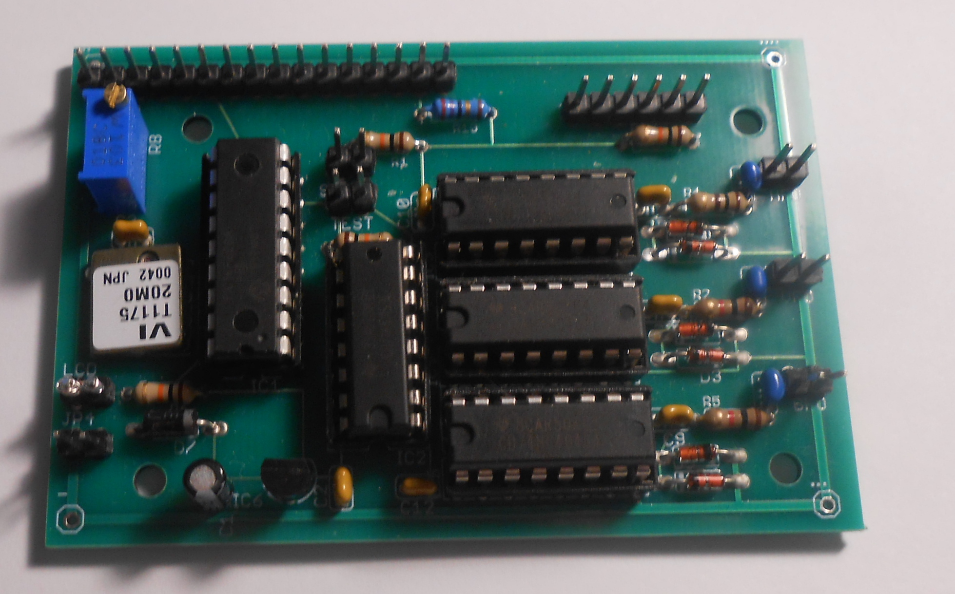
There are
usually many inexpensive TCXO's on eBay. A Veltron
TCXO is
shown
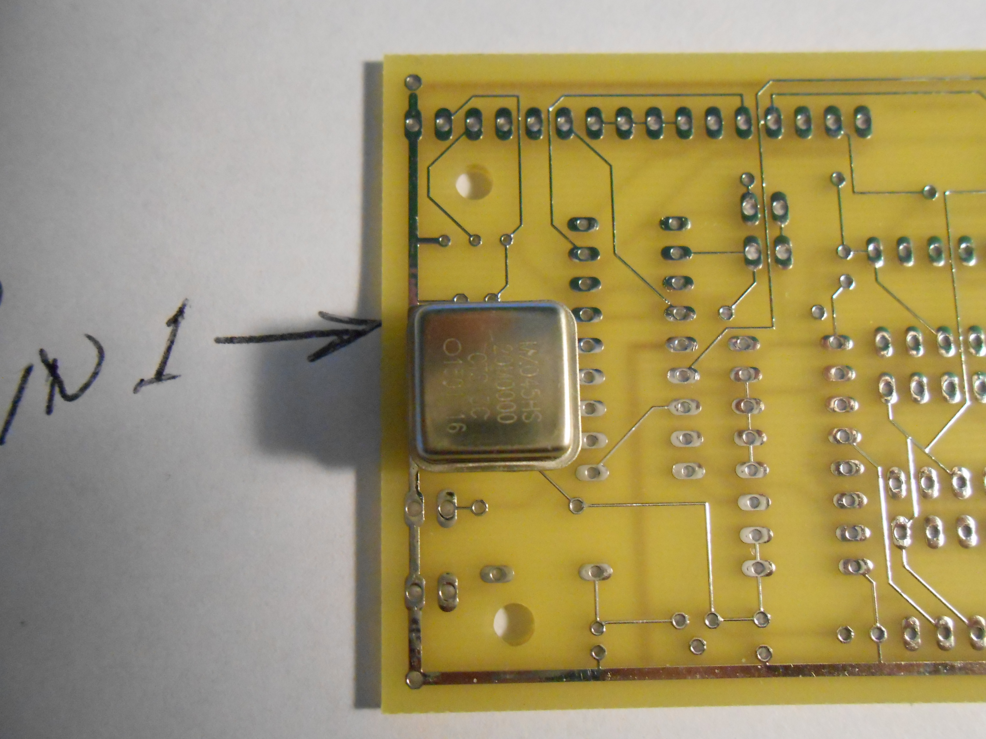
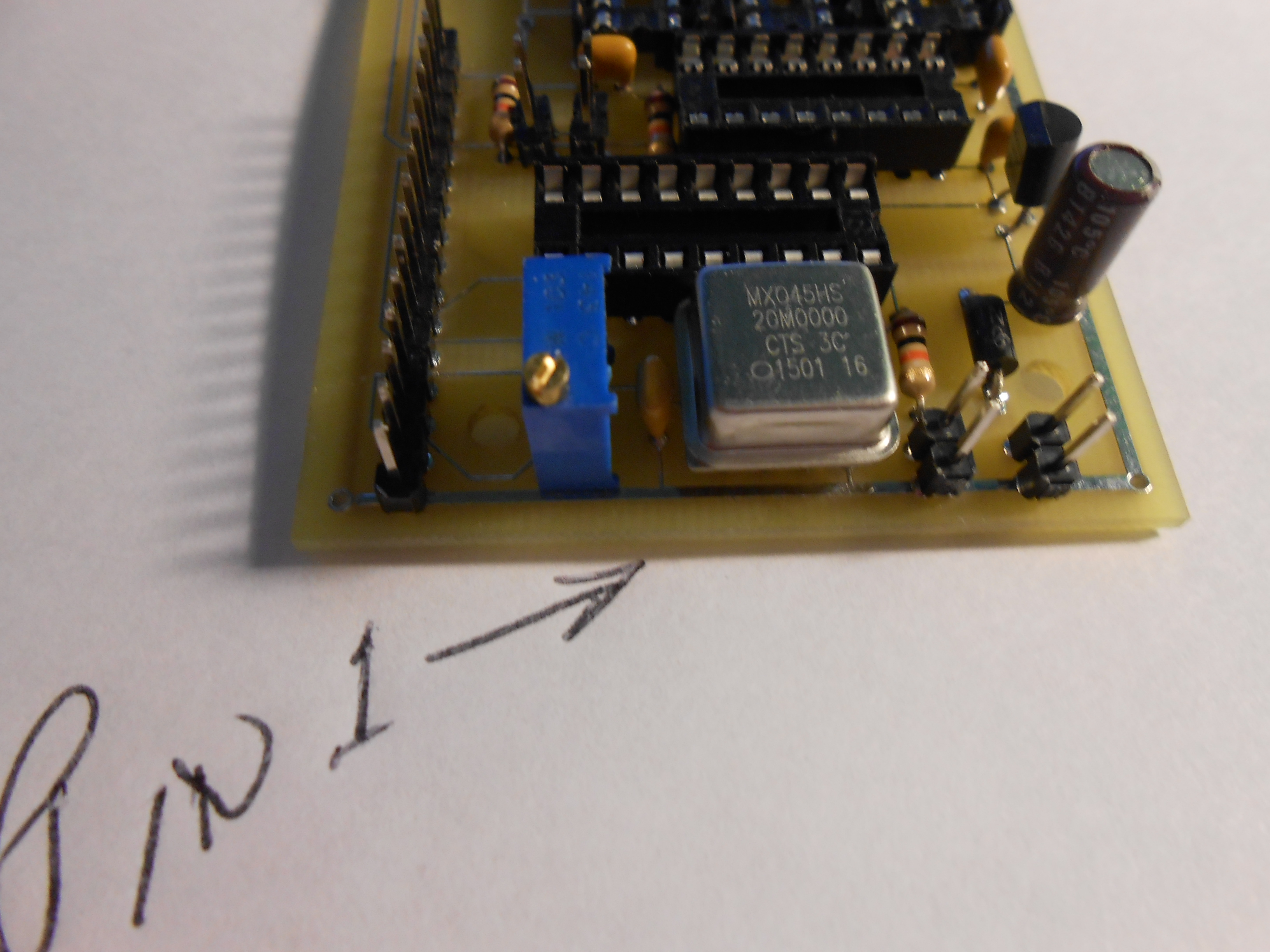
here. In
selecting one, ensure that it as an 8 pin DIP footprint, and that you
mount
it properly on the PCB. Pin #1 is usually marked with a
circle (and a pointed metal pin on the 'canned' oscillators)
and it is mounted just below the LCD contrast trimmer. Here
are some pictures showing how to orient a 'canned' package before
soldering it
-
pin1_1
pin1-2
pin1_3.
If
you are installing an adjustable
surface
mount TCXO,
place some solder globs on the
proper pins and attach a small length of bare 30 gauge wire to each.
Route these wires thru the P/C board holes; center and snug
the TCXO
against the
board. While soldering the first wire, gently press the TCXO
to
the
board. Then, carefully solder the remaining wires,
carefully trimming the
excess
after the solder has
cooled. On some of my boards I used a
Vectron 20
Mhz TCXO
(surface mount), also available on eBay.
Pin #1 is marked
with a small circle on the metal just like the canned oscillators.
Install the oscillator LAST as the shock
from clipping long soldered component leads may jar its frequency
setting.
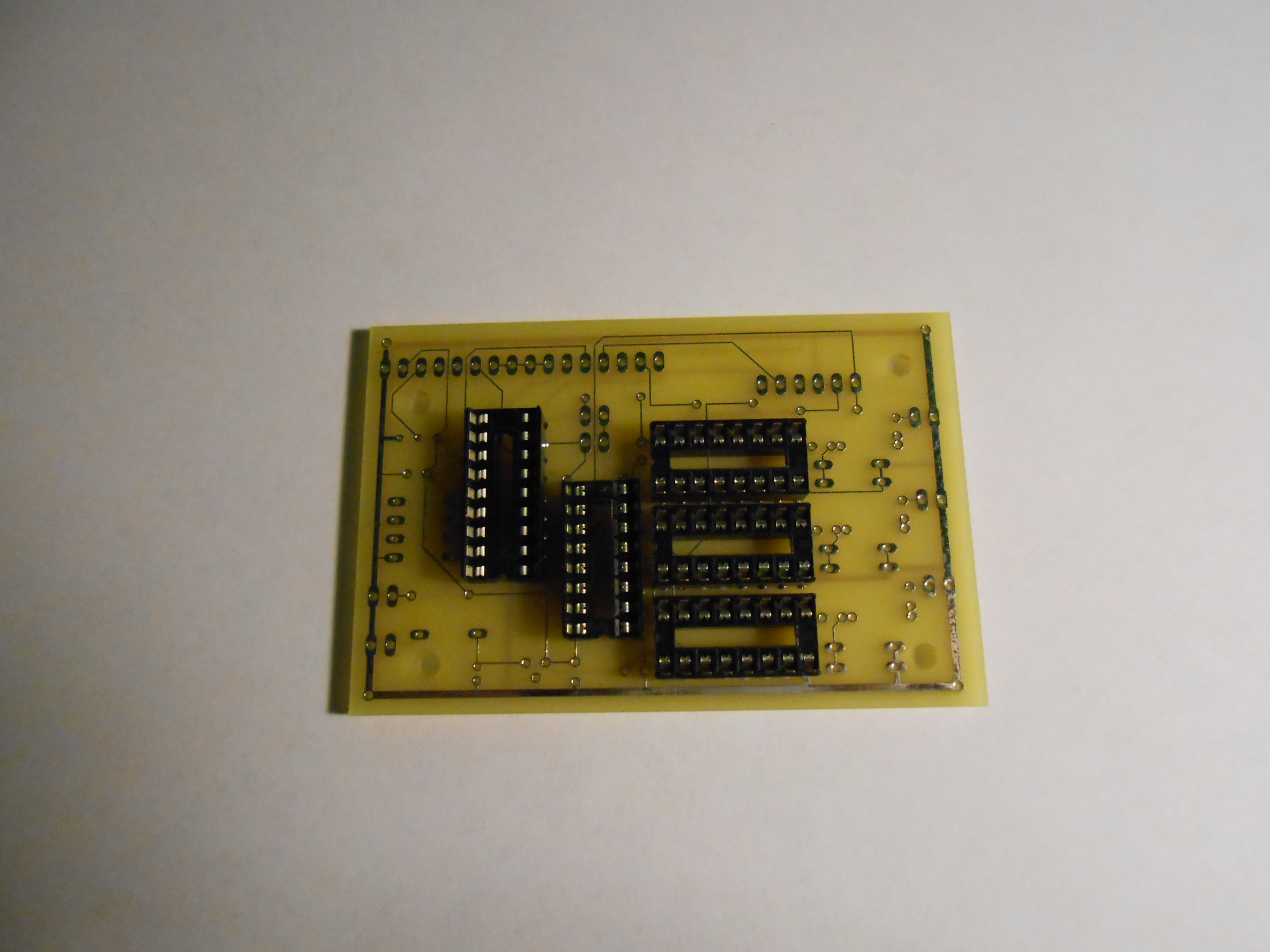
- Install the three (3) 16 pin
sockets
for the HFO, VFO and BFO (all CD74HC4046).
Please
be sure that the notches point towards the inside of
the P/C board.
Ensure that you mount
them on the right side of the PCB and then solder
carefully. Follow
the silkscreen
patterns.
- Install the 16 pin IC socket for
the CD74HC153 with the notch
pointing toward the bottom
of the board.
- Install the 18 pin IC socket for
the PIC16F628A
microprocessor with the notch
pointing toward the bottom
of the board.
- Install
the (7) .1mf ceramic capacitors.
(C2, C3, C7, C8, C9, C10, C12),
- Mouser
594-K104Z15Y5VE5TL2
- Install C4, C5 and C6 - all ceramic .01
mf capacitors,
- Mouser
Mouser does not stock a 25 VDC ceramic that will fit on this
board at this time. Try
eBay as that is where I purchased my .01 caps. DigiKey is
another possible source.
- Install the (6) 1N4148 input protection clamping diodes
(component
names not marked on board) for
the HFO, VFO and BFO (not
required for Darke 2B, 2C),
- Install R4 (100 ohms), R2 (1K ohms) and R5 (1K ohms) - all
1/4 watt resistors).
- Mouser
660-MF1/4LCT52R101G
660-MF1/4DCT26A1001F
660-MF1/4DCT26A1001F
- Install R1, R6 and R9 - all 10 K (1/4 watt)
resistors.
- Mouser
660-MF1/4LCT52R103G
- Install the polarity reversal protective diode D7 (1N4001,
or equiv),
- Install C1 - 10 mf elecrolytic
capacitor (watch the polarity - groundgoes on the outside of the board),
- Install the 5 volt voltage regulator (LM78L05)
Note:
You'll
need a 1x16 (one line) LCD). Connections
between the LCD
and the PCB, and the connections for
power
and for the HFO, BFO and VFO oscillators can either be hard wired with
stranded wire or wire wrapped using 30 gauge wire. I prefer
using 30 gauge wiring. You'll
need to mount pin
headers (shown below). Pin headers are easily broken to
separate them before soldering. I've usually purchased them
on
eBay. They're inexpensive. Mouser also has them
somewhere.
- Install the 2 pin (header) jacks for the 13VDC power (JP-4) and
the HFO,
VFO and BFO outputs.
- DO
NOT install a 2 pin header jack on the LCD. Use a small piece of
30 gauge wire to short the LCD connection points together (may already be done on the PCB you receive).
- Install the 2 pin (header) TEST and the SPARE
jacks.
- Install the 16 pin header for the LCD - eBay normally provides a wide
selection of 1x16 LCDs.
- Jumper the LCD connections as they
won't be used.
- You
need NOT install PICKIT3 pins or resistor R7 as they are
used by me for in-circuit programming use only.
- Install the 10K LCD contrast control (R8). For most LCD's, a
simple wire jumper can be used in place of R10 (see below).
Note: For most of the smaller
LCDs, the on-board regulator will satisfactorily power both the DFD-2
board electronics and LCD backlight. For
LCD's whose backlight draws less
than 23 ma (most eBay
sold units will fall into this category), you may omit the
resistor entirely and use a wire jumper
instead.
If
your LCD display draws more current and the
LM78L05 gets very hot, then power
both the board and the display with
an
external
LM7805 heat sinked to the chassis of the radio to which the
digital display will be connected.
- Install the 4 pin 'canned' crystal oscillator (Mouser - 520-2200BX-200).
This is a 4 pin DIP and it must be properly
installed. Pin #1 of the oscillator has a pointed edge.
Here
are some pictures showing how to orient the package before soldering it
- pin1_1
pin1-2
pin1_3.
- OR
- If
you are installing an adjustable surface
mount TCXO (usually available on eBay),
place some solder globs on the
proper pins n attach a small length of bare 30 gauge wire to each.
Route these wires thru the P/C voles, snug the TCXO against
the
board. While soldering the first wire, gently press the TCXO
to
the board. Then, solder the remaining wires,
carefully
trimming the excess.
- Apply 13 VDC power to JP-4 and
verify that +5 VDC is present on pin 14 of the microprocessor socket,
on pins
15 and 16 of the CD74HC153 socket, and on pins 16 and 3 of the
CD74HC4046 socket.
- Remove the power and verify that ground is present on pin 5
of
the microprocessor, on pins 1, 8, 10, 11, 12, 13 of the CD 74HC153, and
on pin 8 of the CD74HC4046 sockets.
- Connect the LCD display. I used 30 gauge wire
wrap wire
from eBay. It's
quite convenient and flexible.
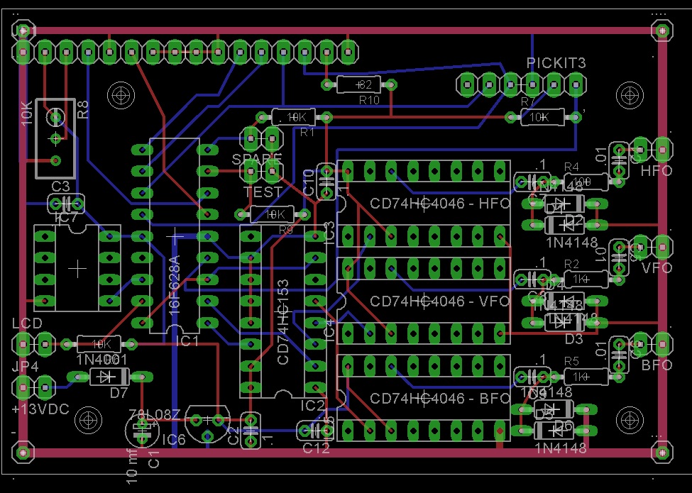
- Referring to the printed
circuit board layout, install the integrated circuits by
straightening the pins (rolling
them on a hard surface) and then my 'rocking' them
in.....noting their orientation. If you encounter
any resistance check it oup before proceeding. .
- CD74HC153
- Mouser
- 595-CD74HC153EE4
- CD74HC4046
- Mouser
- 595-CD74HC4046AE (3 required)
- PIC16F828A - provided in this kit.
- Power
up your board and adjust the contrast control until the display shows
something. Since it will not be connected to a radio at this
point, you'll see a negative number F1572.22 . until the display
has been connected to your radio's HFO, BFO and VFO points.
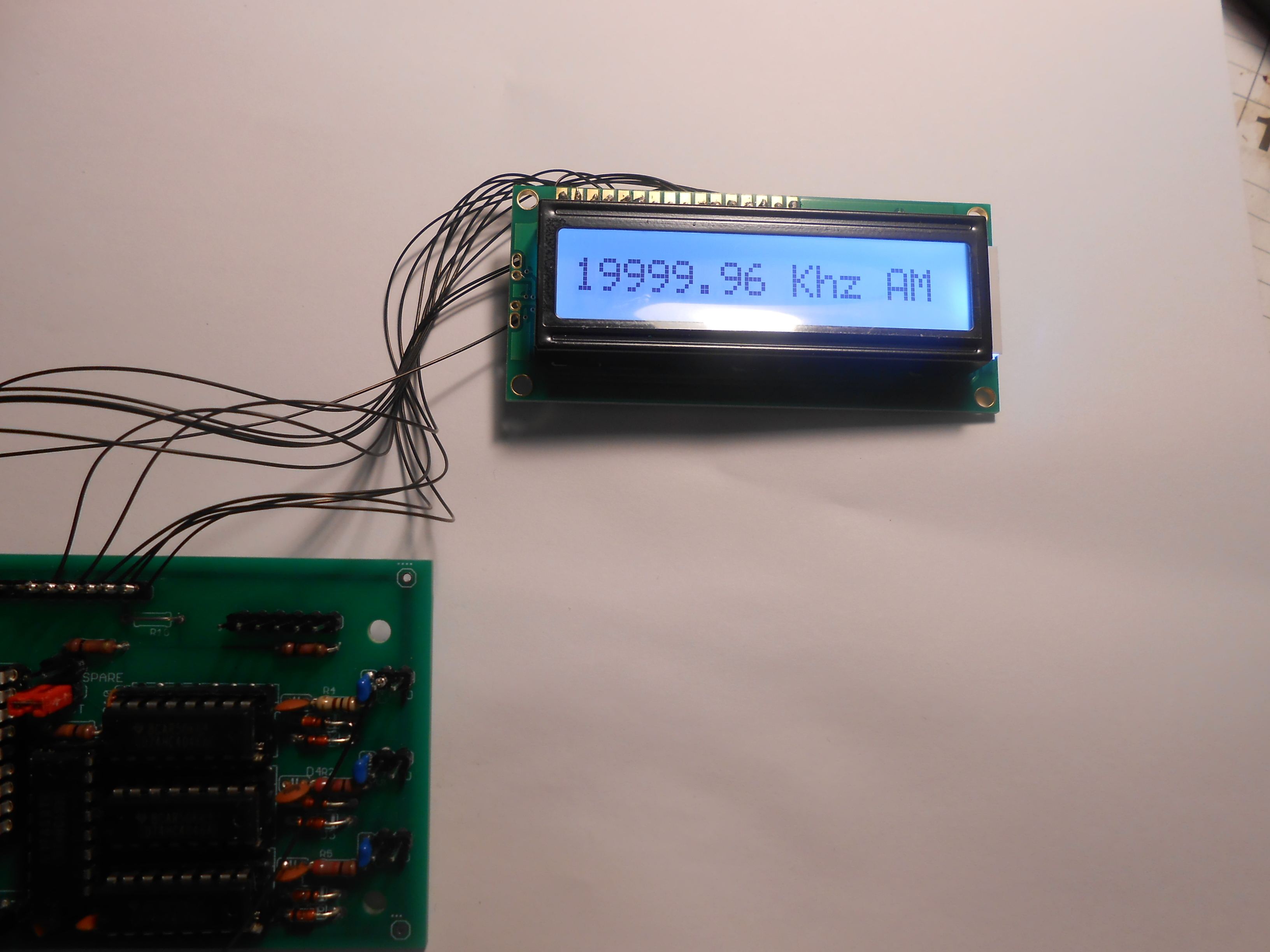
- To
(academically) view the frequency of the master oscillator, jumper out
the TEST
connections and connect the output of the oscillator to the HFO input.
You'll see something like this.
6. Enclosure Suggestions
You may be able to find an
old radio Shack plastic enclosure on eBay I used
the smallest I could
find (5 x 2.5 x 2 inches) that would hold
the
electronics which is stock number 270-1803 ($5.49). Amazon is
also an excellent recent source. The
plastic in
these
boxes is easily cut
with an Exacto
(or similar) knife, and some may be available from eBay
scalpers.
- connect the board to the LCD (using 30 gauge wire) and then
test the complete assembly.
- cut a hole for the LCD in the lid and mount the
LCD,
- mount the board in the rear of the box leaving space for
the interface and power cables (you may install RCA jacks, etc if you
so desire),.
7.
Connecting It
Using 2 to 3 foot lengths of RG-174 (or
equivalent), install
PHONO plugs on one end and and solder the other end to the HFO, VFO and
BFO
P/C board connection points. Either tag or color code these
connections and insert them into the SB-300, SB-301, SB-303, SB-310,
SB-313, TS-520S
(etc) radio of your choice and the appropriate jacks will have already
been placed on the radio's rear panel. These are the easiest interfaces.
Some minor additional work will be required for the HW-100,
HW-101, SB-100, SB-101, SB-102 (see below), and to the HR-1680.
Note: You
may need to
repeak
the HR-1680 heterodyne
oscillator
(HFO) adjustments as
the additional capacity may detune
them somewhat.
Also Note: If
connecting to an SB-303 / 313, place a 47 ohm resistor across the VFO
coax connection from the radio to the DFD-2. If this resistor is not placed, the frequency display may become intermittent.
Also Note:
If you are mounting the
circuit board on your radio's chassis, ground each of the 4
mounting holes by soldering a small
gauge wire from them to the ground that 'runs' around the side of the
board. Use spacers so
that the board does not
'ground out'
when mounted.
8.
HW-101 Interfaces
- All connections are made at the cathodes of the various
oscillator tubes.
- All
connections are made through a 27pF cap and RG-174 coax. 27
pf
was found to provide adequate coupling without loading any stage.
- HFO connection at pin 7 of V11
- VFO connection at pin 7 of V12
- BFO connection at pin 9 of V13
- Bypass (Jumper out) the input .01 and the 1 K resistor on
the HFO input circuit of the counter if it will not count above 15
meters.
- Keep cables as short as possible.
9.
HR-1680 Interfaces
As in the case of the Heathkit SB / HW
series, connections are required to the HFO, VFO and BFO
points within the radio. These connections - made with
miniature
coax (RG-174 or equivalent) - are sent through a small capacitor (from
30 to 60 pf). The HFO and VFO
connections are made on the underside of the
chassis, whereas the BFO
connection is made on the AUD / REG circuit board (D). The
BFO
connection is made at the top of the board with the shield of the
coaxial cable terminated on the rear of the board.
Note: When
making the BFO connection, be sure to leave enough coax so that the AUD
/ REG circuit board may be placed on an extender should service ever be
required.
Suitable RCA phono jacks are mounted on the radio's rear panel where
there is also a convenient source of 13 VDC.
Important Note:
Connections to the SB-300 / 301 / 303 are very simple as Heathkit
designed these radios with suitable pick-up coils on the Heterodyne
Oscillator specifically to send the HFO signals to a matching
transmitter. With them, it's just plug 'n play'.
Connections to the SB - 100 / 102 / 102 and to the HW-100 /
101
are a bit more involved in that the HFO, VFO and BFO signals can be
picked off the cathodes of the respective tubes. The
HR-1680 conversion is a bit more involved if operation
on 15 and 10 meters is contemplated. While the display will
work
with direct connection (via a small capacitor) to the HFO output, the
additional capacity on these overtone crystals may attenuate the HFO
output and the
received signals.
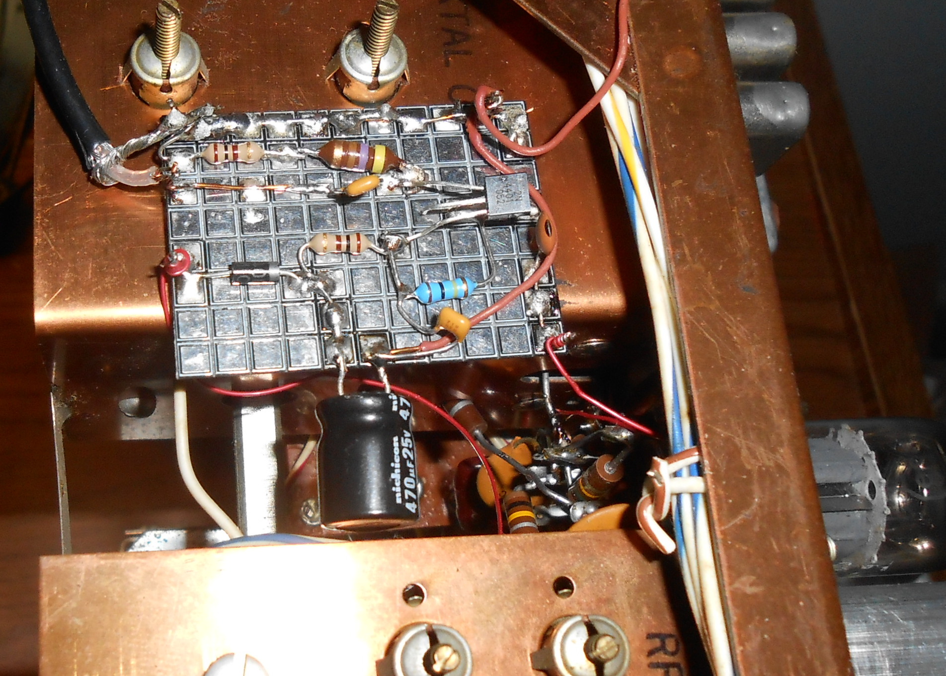
To solve this problem, a small 2N3904 emitter follower circuit is
mounted it under the chassis (on double sided tape), as shown here.
With it, received signals are significantly improved
on the higher frequencies.
Also Note:
This is the same circuit as the HFO buffer used in the Kenwood TS-520
radios. It
works!
10.
Drake 2 Series Radios - see schematic
If you are building
your own board, please follow the instructions shown
here.
The same
DFD-2 Interface Board (but
with a different
program) can be used to provide digital dial display
capabilities.
The
BFO input is not used in this conversion.
Connections are
made from the DFD-2 board - using RG-174 miniature coaxial cable - to
the Drake's Heterodyne Oscillator (HFO) and to the Drake VFO circuit.
As in the case of the HR-1680, a simple buffer circuit (shown
on the schematic) needs to be constructed so that the HFO
signal will have sufficient amplitude to drive the DFD-2 circuit.
Those who don't regard their unmodified Drake 2B as a potential
priceless heirloom may decide to install 2 RCA Phono jacks on the rear
panel. Others may decide to run the coaxial connections
through
the existing rear chassis ventilation holes. Here are the connection
points along with some pictures:
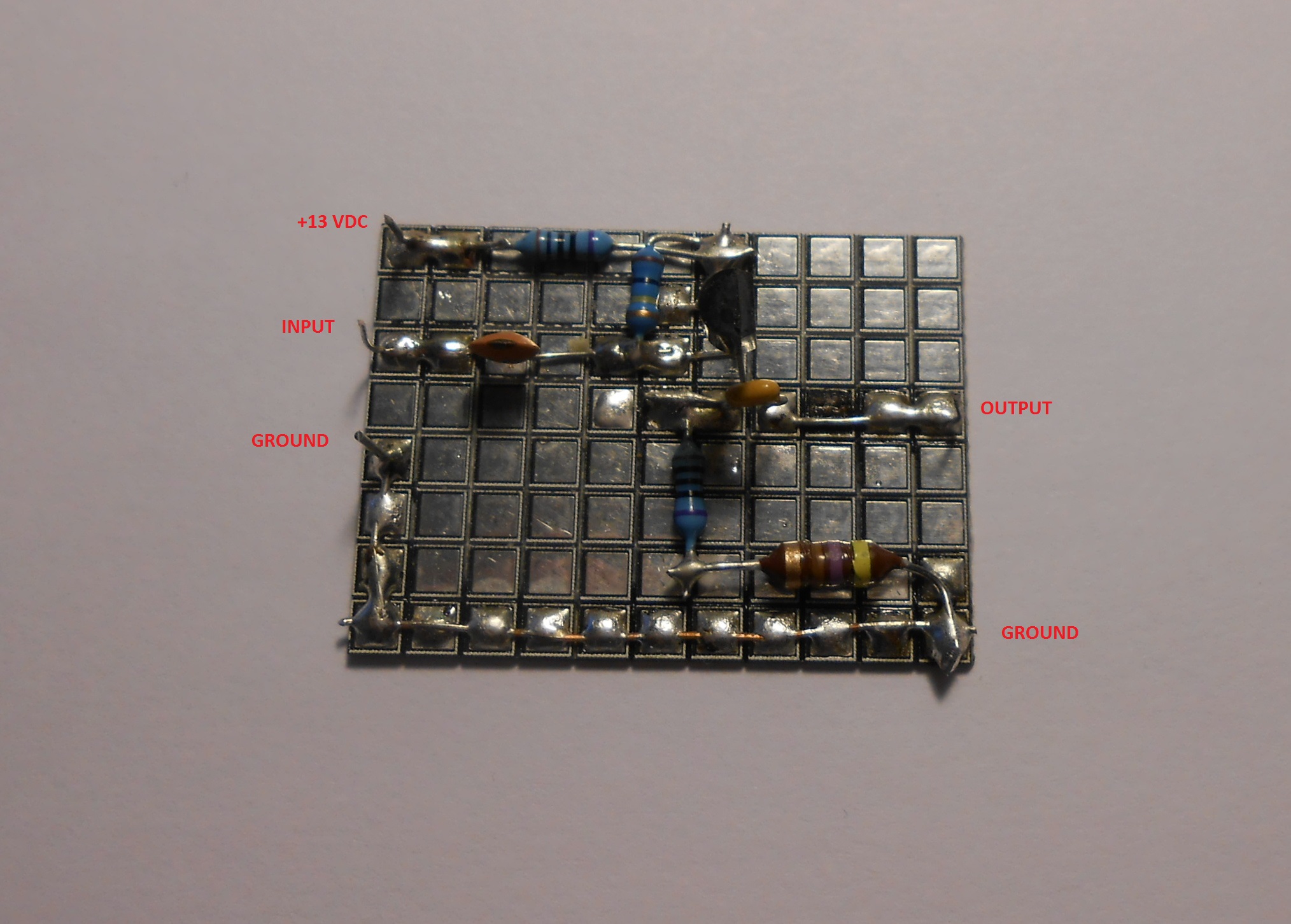
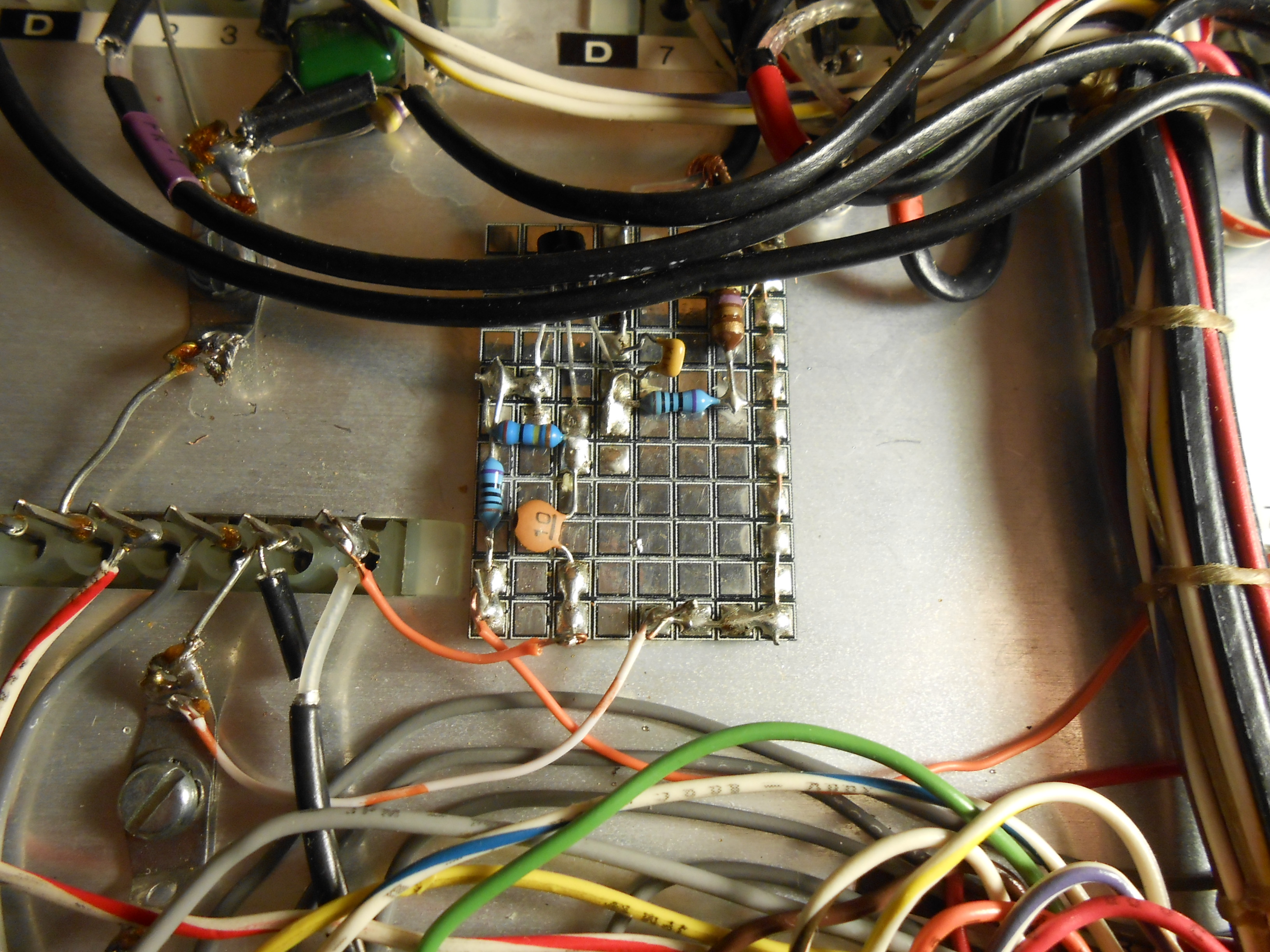
- The HFO buffer (emitter follower) circuit is constructed on
a small piece of Me Squares
from QRPME.com,
and then epoxied between the tuning coils on the side of the radio (as
shown). The input side of the HFO buffer is
connected to the
cathode (pin 8) of V2, the crystal oscillator tube (6U8A). This is the same circuit as the
HFO buffer used in the Kenwood TS-520 radios and also displayed on the
inactive AADE website. It
works, even at 7.7 volts DC (rectified and filtered
filament voltage).
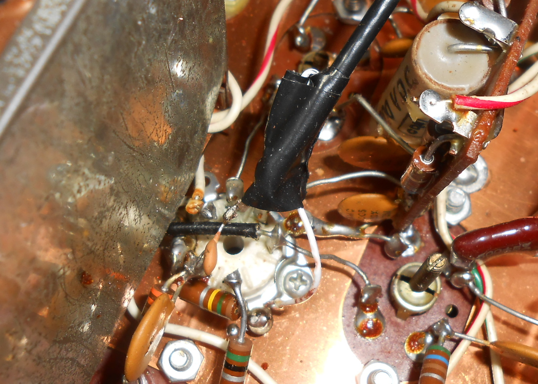
- The
VFO connection
is made - through a 20 pf capacitor - to the cathode
(pin 2) of V3, the VFO and second mixer tube (6BE6) - with the coax
shield connected to a ground point.
- Drake 2 C Conversion: -
I don't have a 2C,
but have included the service manual. The
HFO will be picked off the solid state HFO (don't know if a buffer
board will be required), and the VFO connection made - as in the 2B -
off pin 2 of the VFO and second mixer tube.
When I originally coded the PIC, I set it up so that it would
automatically detect the XTAL HFO frequency and 'know' when to either
add or subtract the VFO. However, because Drake slyly decided
to
use a single 25 Mhz crystal for 21 / 28.5 Mhz (15 and 10 A meters), a
switch was needed whenever the 25 Mhz crystal was selected. Now,
since an outboard switch was necessary, I decided to let the user
decide whether to add or subtract the VFO on any band.
This way
any crystal can be used that is permitted within the preselector's
tuning range. It's easier said than done., e.g.:
- In the DOWN
position - 80, 40, 20 and 15 meters are enabled.
- In the UP
position - all of 10 meters (if your radio has the appropriate
crystals).
Note:
To ensure 'spot on' accuracy, ensure that your radio is aligned
properly. Pay particular attention to the 50 and
405 khz
oscillators. Get them right and you'll be rewarded by
exceptional display accuracy. Align the radio when it's been on
for an hour or so. My Drake's 405 khz oscillator
will drift a bit after it's first turned on - Your mileage may vary.
Any
drifting has to do with the 2B / 2C itself - not with the display which
is clocked by a TCXO.
Drake 2B
'Birdies' - Insignificant
You may notice some low level birdies here and there as you tune across
the bands if the radio is out of its cabinet and if no antenna is
connected. Some of these are entering the radio via the front
end
circuitry as they become stronger as the preselector is peaked.
However, with the radio placed back in the chassis,
and with an antenna connector almost all - except for one on 10 meters
- are obliterated. In
this regard, the Drake DFD-2 application is
cleaner than some of the others I've tried.
11. Kenwood
TS-520S Interface
The Kenwood interface is a simple as that of the Heathkit SB-300, 301,
303 (etc). One simply plugs the HFO, VFO and BFO (Carrier)
plugs
into the rear mounted jacks,
applies power to the unit and everything should work FB.
Power (12VDC) can be suppiled via an inexpensive wall-wart and / or is
available from the radio itself on the VFO shorting plug.
Good luck
on
finding the original GD-5 plug that powered the DG-5 digital display.
Small female jacks can readily be installed on the TS-520S rear
panel to provide a source of fused 12VDC for your counter - just attach
the lead to the DG-5 connection points.
The only other comment worth mentioning concerns the modes that are
displayed after the numerical frequency. While the numerical
display will ALWAYS
be correct (because the current VFO and BFO
<carrier oscillator> and subtracted from the HFO), there
might be
some occasions where the wrong mode will display. This is
because
the TS-520S oscillators may have slipped slightly out of their original
settings over time, or were just not aligned properly in the first
place. To correct this, one might take the radio apart to
align
the Carrier Board (which is an admirable - but an involved
proposition).
Once again, rest assured that the
displayed frequency will always
be spot on.
12.
Testing It
The digital display needs a permanent source of 13 VDC power.
This can be accomplished by using an appropriate wall-wart,
or by
deriving the power from the radio itself. If the radio is
driven
by a 13 VDC source (like
the SB-303 or the HR-1680), then a suitable
power source can be found within the radio. If you
want to
power the display from a tube type radio, then you'll have to derive
the power from the filament circuit by using a simple voltage doubler
and
rectifier combination (google it).
Once you have verified that the proper voltages
are present on the IC's, you may install the integrated circuits and
make the connections to the LCD. Connect the digital display to your
radio and apply power. Adjust R8 for the proper contrast.
Switch on your radio and verify that some frequency is being
displayed.
13.
Calibration
If you are using the 'canned' oscillator (Mouser - MXO45HS-3C-20M0000),
no
calibration is required. It should be smack on.
Just to
verify this, (for heathkit programmed DFD-2's) you might want to place
a temporary jumper across the TEST
pins which will make the DFD-2 work as a general purpose frequency
counter up to 50 Mhz, or thereabouts. The HFO input will
record the frequency to which
this
lead has been connected - for example - the crystal
oscillator's output.
If you opt to use a mechanically
adjustable TCXO (wired
with 30 gauge wire the the canned oscillator's connection points),
connect the output of the HFO to the oscillator's output and adjust the
display for 20 Mhz - or just monitor it on a very accurate receiver.
All
the TCXO's that I purchased on eBay and installed on pre-assembled
boards did not require any tweaking - they were apparently set at the
factory. I did notice - however - that their accuracy was off
a
bit after they were soldered inton the circuit. Allowing them
to
properly cool solved this problem. After all, they are temperature
compensated, right :-)
14. Birdies
Most every radio equipped with a digital frequency display has its
share of internally generated 'birdies'. Anyone who has used
rigs
like the Ten-Tec Digital Century 21, the Ten-Tec Omni series or even
the Drake TR-7 will confirm this phenomenon. Therefore, it should come
as no surprise that the DFD-2 Clone will generate some low level
'birdies' - here and there. In most cases though, normal band
atmospheric noise will render them largely unnoticeable.
a) SB-300 Series
There are some
very minor 'birdies' that I noticed on my SB-300. Whether or
not they
will appear on your radio is anyone's guess. Normal band
noise
should mask them out, and grounding the P/C board directly to your
radio's chassis will further attenuate them (none caused the S
meter to 'twitch'):
- 80 meters - 3649, 3700, 3734, 3866, 3903
- 40 meters - none
- 20 meters - 14032, 14198, 14212, 14239
- 15 meters - 21050, 21197, 21371, 21403,
- 10 meters (A) - 28077, 28397, 28456
- 10 meters (B) - 28502, 28749, 28814, 28895
- 10 meters (C) - 29049, 29134, 29323, 29400
- 10 meters (D) - 29510, 29699.
b)
HR-1680 Series
The unmodified radio - with no antenna connected - will exhibit
'birdies' that are strong enough to move the S Meter at 3652 Khz, 3738
Khz, 7030 Khz and at 21200 Khz.
15. YAESU FT-101
- Software Not
Written Yet!
Cabling Options:
1) You may use the remote VFO plug (octal) if:
- You are sure that you, or anyone else will never
want to install a Yaesu remote VFO;
- You have a spare octal, male plug;
- You are willing to work in a very restricted space.
2) You may bring cables out of the rear of the rig
and terminate them with RCA or
BNC connectors at the Digital Frequency Display unit if:
- You are not concerned with affecting the resale value of
the FT-101 by drilling
holes in the rear panel;
- You want to avoid soldering to an octal plug in a very
congested location.
3) You may install RCA or BNC chassis mount jacks on
the rear panel if:
- You want the modification to appear as inconspicuous as
possible;
- You don’t want cables that cannot be disconnected at the
rear panel;
- You are willing to very accurately measure and drill
mounting holes in a very
small space.
Yaesu FT-101 Signals
The BFO signal (3.1793 MHz) is
approximately a 3 volt
(peak-to-peak) signal that may be
tapped in either of two different places. It appears on pin 6
of board 1184A and is
carried by a short piece of coaxial cable to pin 5 of board
1183A. Each board has a
convenient grounded pin for shield connection, but board 1183A is
easier to reach with a
small soldering iron.
After routing the new cable (or
mini-coax, which ever you have
chosen) from the rear
panel to the area of the board chosen, solder a .01
disk ceramic capacitor to
the center conductor of the cable. Then solder the free lead
of the capacitor to the
chosen pin of the board edge connector and the shield to the nearest
grounded pin on the
edge connector.
The Local Oscillator signal
(approximately 6MHz above the
displayed signal, or 8 to 36
MHz) is approximately a 3 volt (peak-to-peak) signal that is available
at the test point
near the top edge of board 1181A.
You have 2 cabling options
here. The first option is
to route the cable from the
rear panel toward the front of the transceiver, and the openings around
the tuning
dial. Use these openings to pass the cable to the top of the
chassis. While
viewing the FT-101 from the normal operating position in front of the
rig, route this
cable up over the tuning shaft and to the right of the
chassis. Solder a .01 disk
ceramic capacitor to the center conductor and a small ground lug to the
shield.
Solder the free lead of the capacitor to the test point at the top of
board 1181A,
and attach the ground lug under the adjacent control’s mounting nut and
lock-washer.
CAUTION. This method of installation means that you must
disconnect the ground lug in
order to remove the board from its edge connector.
AN ALTERNATIVE installation method is to install the blocking
capacitor (.01 disk
ceramic) on the board between the test point and unused pin
15. This will allow easy
removal of board 1181A. However, it
requires soldering the coax to the
edge connector for board 1181A in a very congested area. In
this alternative
installation the cable stays on the underside of the chassis and is
soldered to pin 15,
with the shield is soldered to pin 18 of the edge connector for board
1181A.
The VFO signal (approximately 9 MHz) is about a 1 volt
(peak-to-peak) signal available
at pin 11 of board 1180A. After routing the cable from the
rear of the chassis,
solder a .01 disk ceramic capacitor to the center conductor.
Solder the free
capacitor lead to pin 11 and the shield to pin 10 of board 1180A.
(The VFO signal also appears on the remote VFO adapter (octal)
plug. In the beta
unit this signal appeared to be a little dirty causing erratic
operation until the unit
had warmed up for awhile. This may be peculiar to that one unit.)
Copyright
2020, 2021, 2023, 2024 K3JLS - All Rights Reserved - Software Included