Replacing
Problematic Digital Displays on the Ten-Tec Omni Series Radios with a
State-of-the Art 6 LED Unit
How
many of you folks out there have an old (but reliable) Ten-Tec Omni
A,B,C or D radio whose front panel display has become intermittent,
most probably because the counter chip has become flaky and / or one or
more of the LCD segments has disappeared?
The
product described below will nicely solve that problem with a minimum
of work and can probably be retrofitted into the analog Triton, into
the older Argonauts, and so forth.
It can readily be used to provide a digital display for the 'slide
ruled' Omni A's.
Essentially,
it's a custom
programmed and very inexpensive Chinese
6 digit frequency counter that will
provide a plus or minus 9 Mhz offset when a pin on the rear is
grounded. This display has an onboard 13 Mhz TCXO, is
electrically 'quiet' and is extremely fast and accurate.
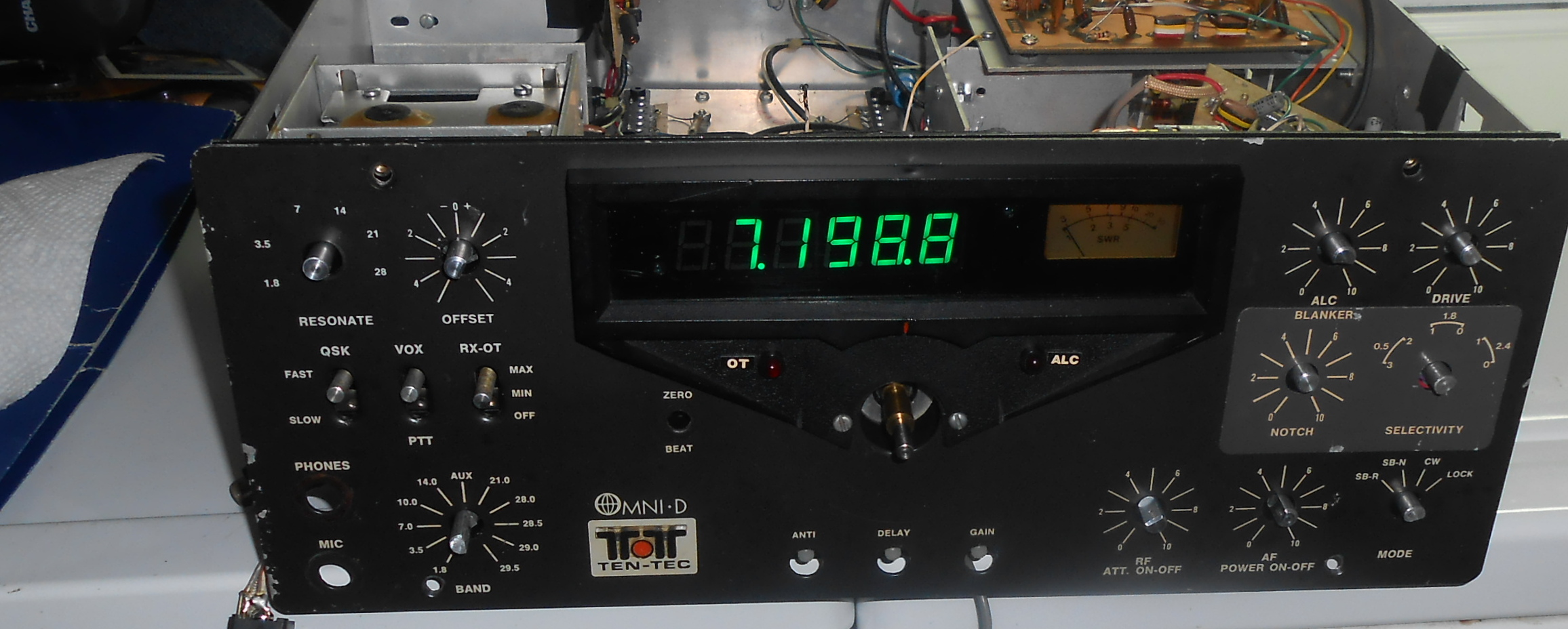
Best of all, it
will easily fit into the space vacated by the old display, and the
result will be virtually indistinguishable from the stock factory
display except that all the digits will be the same color.
There are currently two versions of the 6 LED both
of which provide the same output and which are programmed slightly
differently (I take care of that). The older board,and the newer board. These are described later.
If you are interested, you may want to contact
me to arrange for the programming of a 6 digit display (if
you already have one), or to purchase a pre-programmed one from me.
FYI -
The proprietary code I wrote for the PIC16F648A processor consists of
two
elements - the frequency counter portion and the LED serial
driver.
NOTE:
Perform these modifications at your own risk. I will not be
responsible if you inadvertently damage your radio.
These are general instructions to complete this upgrade which should be
easily accomplished by anyone with moderate technical skills.
1)
Remove the radio's knobs and front panel.
2)
On the old display, unsolder the power (red) and two control leads
(various colors), remove the display support bracket and the display
itself, etc.
3)
Cut a piece of plastic to fit in the opening where the Ten-Tec display
formerly was. On
the inside
of the front panel, rest it on top of the PTO and trim the
top to
fit. Ensure that it's wide enough so that
mounting screws
can hold the sides and the bottom.
4)
Drill holes in the plastic corresponding to the existing front panel
holes, but don't permanently mount it yet.
5)
Using a dremel tool or another sharp object, cut a rectangular hole to
accommodate the 6 LED display and them mount both the display and the
board itself. Cover any exposed screw heads with black
electrical tape. The black tape will also mask any
imperfections in cutting the rectangular hole.
6)
To make the display automatically add or subtract the 9Mhz frequency,
turn the radio over, identify the proper wafer on the bandswitch and
remove both ends of the short brown wire (it provides 12
VDC).
Note:
These bandswitch contacts are not avaailable on the Omni A series, nor
in the analog Triton, Argonaut, analog Argosy (etc). To
upgrade these
radios either a new front panel switch needs to be installed or the
activation mechanism for the crystal calibrator may be repurposed.
With an
accurate digital display, who needs a crystal calibrator anyway?
7)
Ground the terminal to which the brown wire was connected.
8)
Turn the radio on, rotate the bandswitch and verify that the lead is
OPEN for 160, 80, 40, and 30 meters, and GROUNDED for the other higher
bands. The
must be no voltage present on this lead or the display will be ruined.
9)
Use the wire
from the modified bandswitch to connect to the
display's CONTROL POINT (lug right next to the triangle - see pictures).
10)
PLEASE READ BEFORE APPLYING POWER.
Connect 13 volts and ground to the 6 LED unit. Please note
that the power connector is at the end of the board with the two push
buttons (no longer work), the voltage regulator, the protection diode,
etc. The positive and negative connections are clearly marked.
You will be getting two plug in control leads with your display,
one for the power connection and the other for the input signal
connection. If you plug one of the cables into the power
connector and the red wire happens to end up on the negative side of
the board connector - don't worry. Just connect the black lead to
13 volts and the red lead to ground. This unit has a series blocking
diode to prevent damage to the electronics when the power connections
are reversed. Connect the power leads first and verify that the
display illuminates. Power the radio down.
11) On the
other end of the board (you'll see two signal clamping diodes) are the
connection points for the signal input and coaxial cable ground.
Plug in the remaining cable, and connect the shield of the coax
cable to the wire that goes to the board's signal ground, and the other
lead (marked with a sine wave) to the center of the coax. Power the
radio back up and verify that the display records the proper frequency
as the shaft of the PTO is turned.
12)
Reassemble the front panel, knobs, etc.
13) Ensure that your radio is properly aligned and then enjoy your new
display.
73's - Joe - K3JLS