1. Introduction
A control head needs to be constructed. You can personalize your conversion to suit your needs. The frequency, CTCSS and channels are entered via the keypad. The volume is set in the normal manner and the squelch - since it is most often fixed, can be left at the radio itself by installing a trimmer potentiometer. However, a control head squelch can be provided as well, if the user desires one.
2. Building the Control Head
Here's one suggestion.
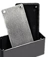
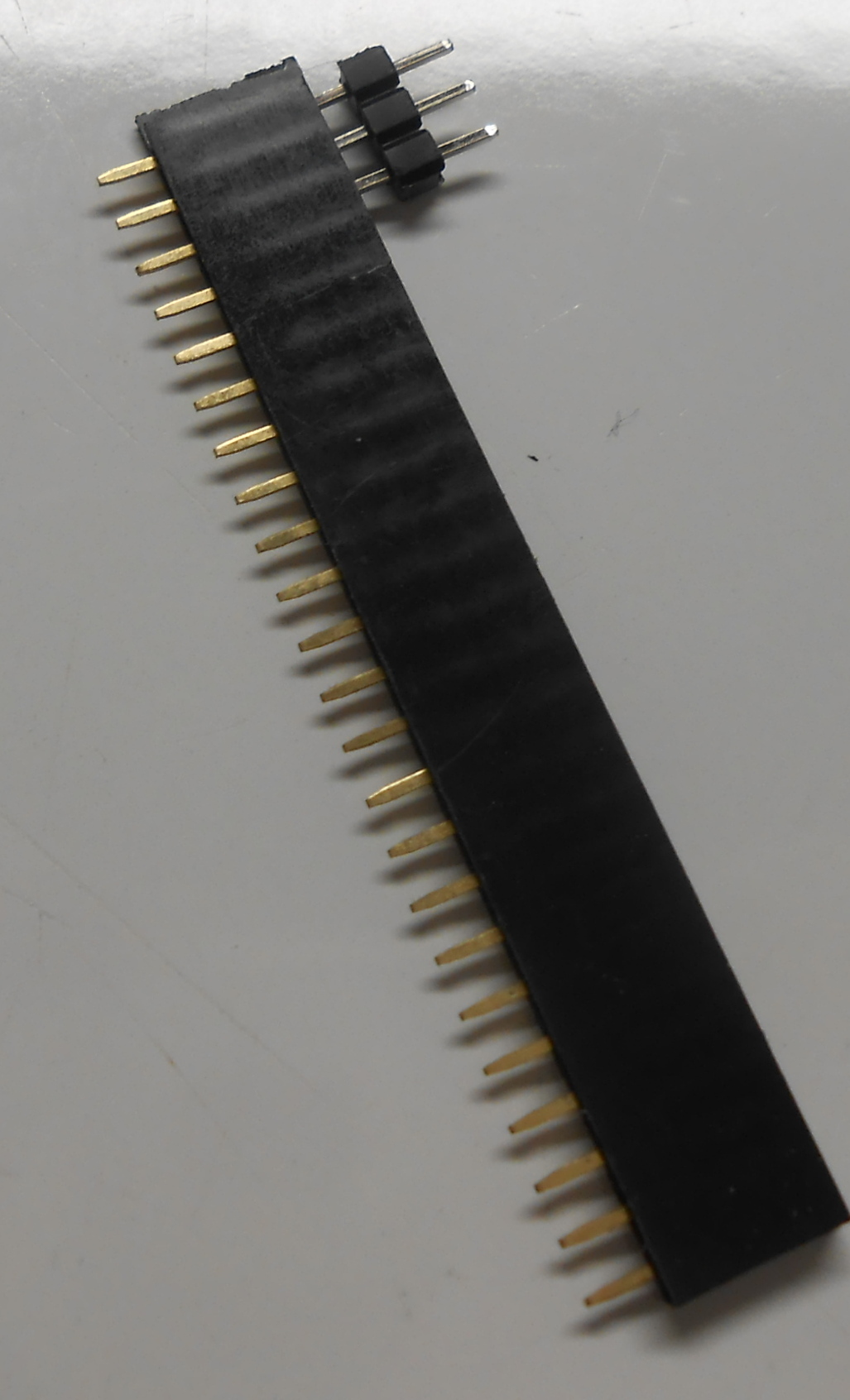
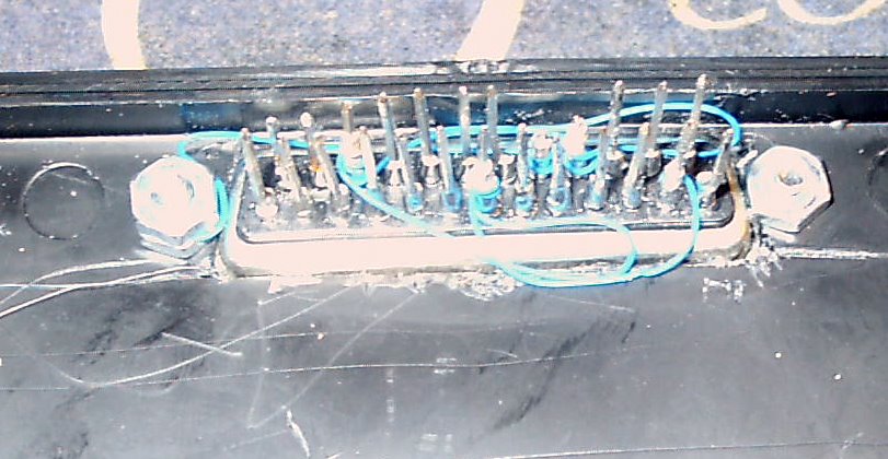
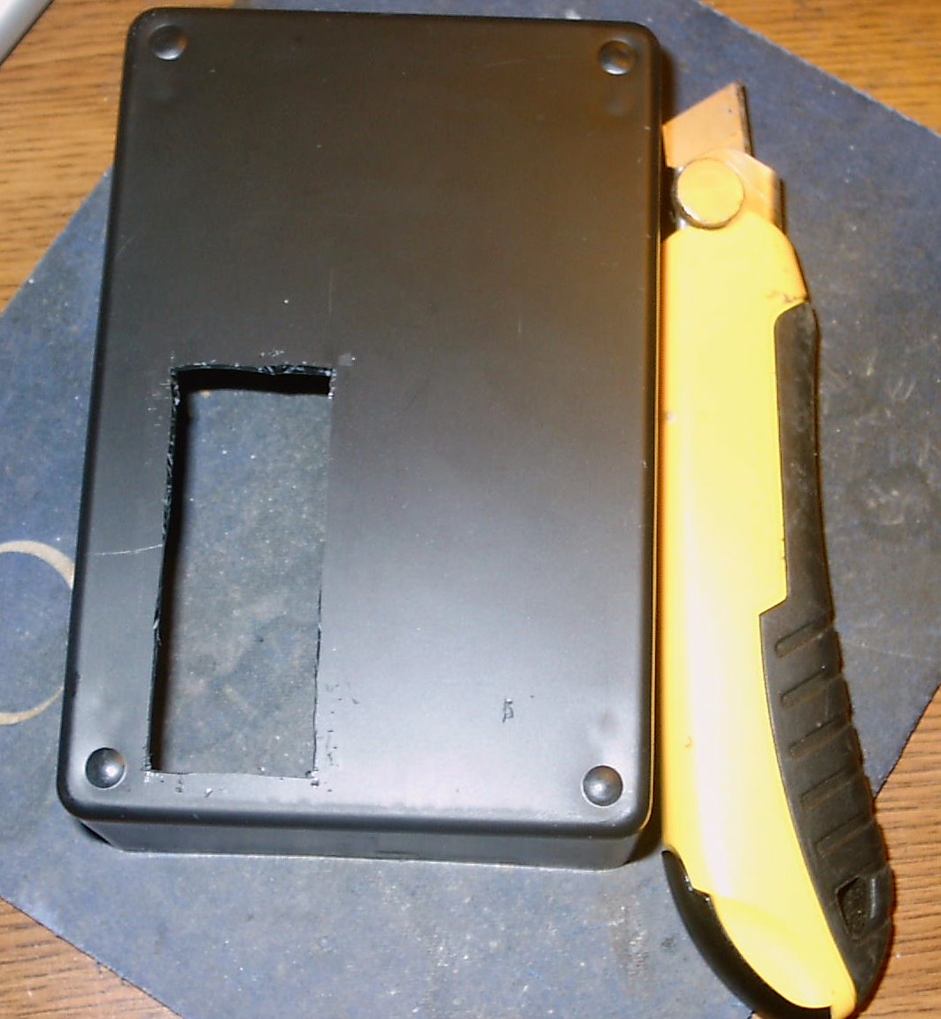
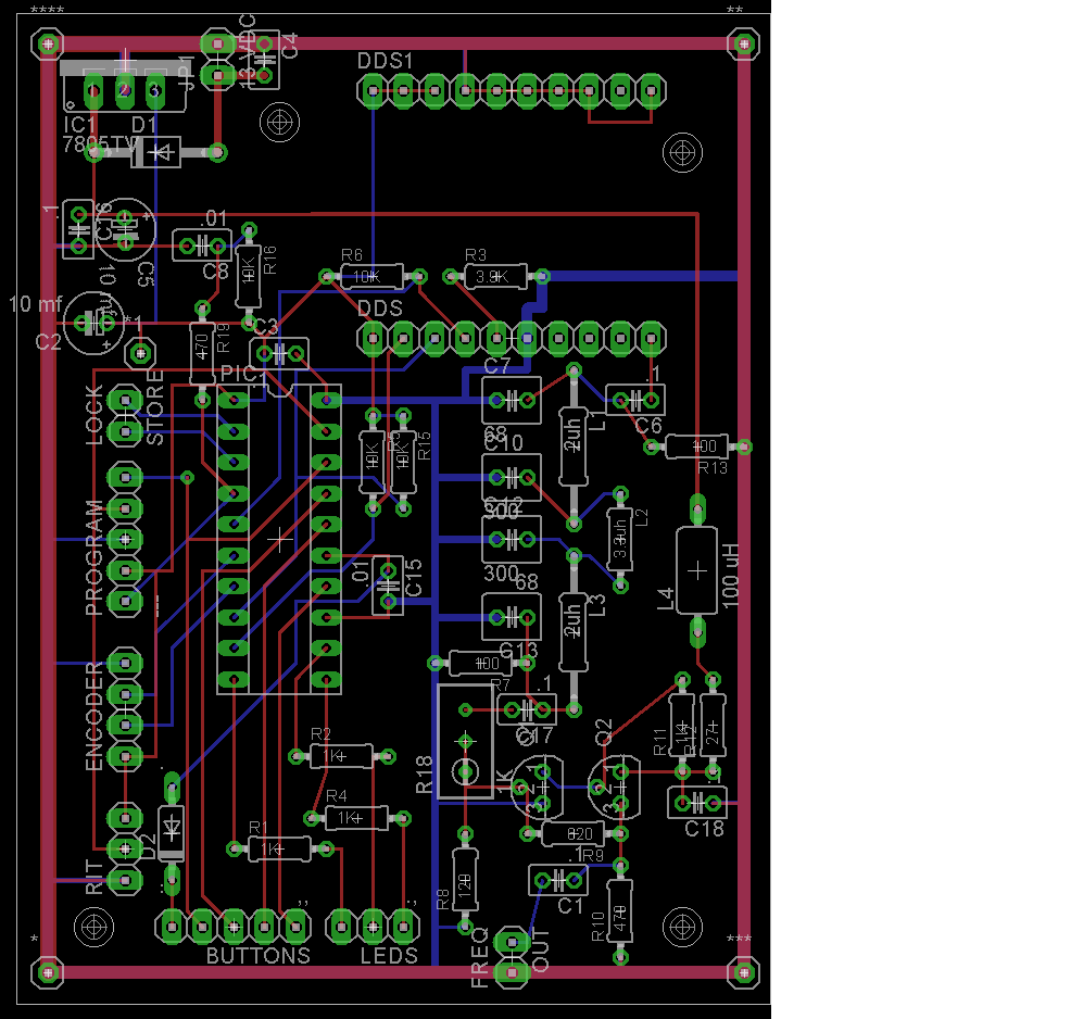
Get the larger Radio Shack plastic enclosure (270-1806), one whose rear side is large enough to hold the 3.5 x 4inch P/C board. Solder pins to the 25 leads in a Male DB-25 connector. Use stiff pieces of wire, leads from larger resistors, pins from wire wrap sockets, or spare pins from the pin headers purchased for your P/C board connections.
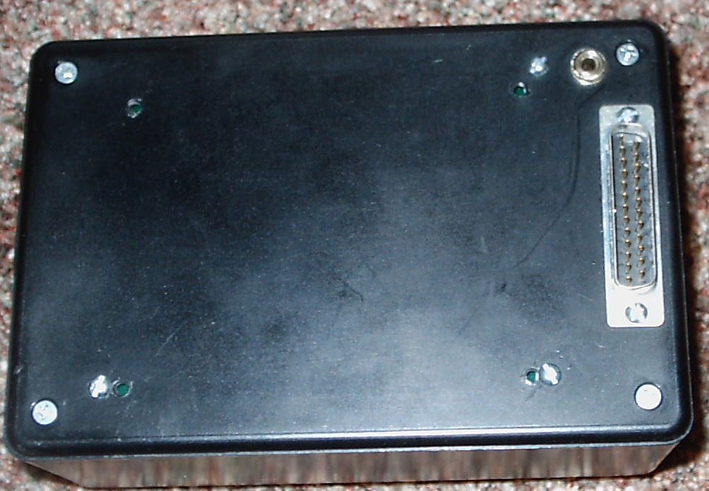
On the rear section, make an opening for a DB-25 connector. The plastic box is already slightly scored where the connector will mount. Use an X-acto knife to make the hole. and mount it in place. Once mounted, make the shield and ground connections with 30 gauge wiring.
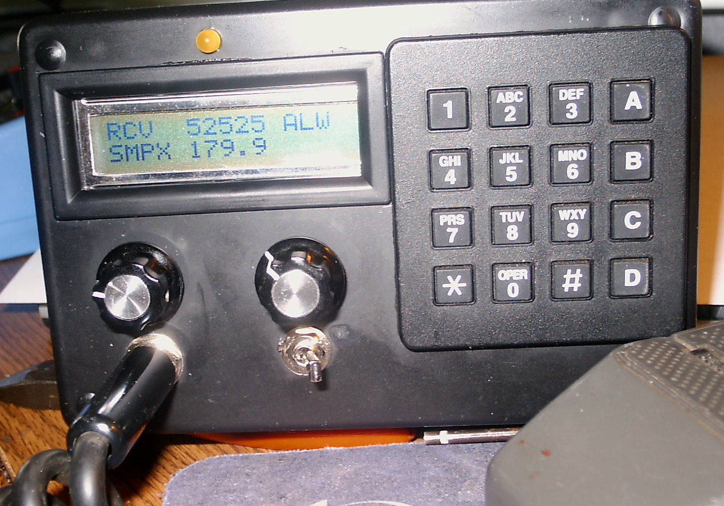
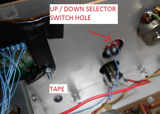
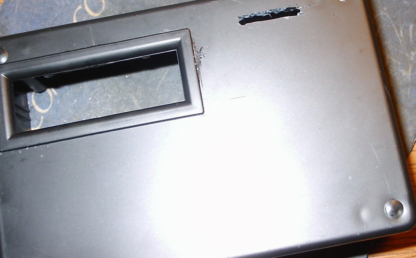
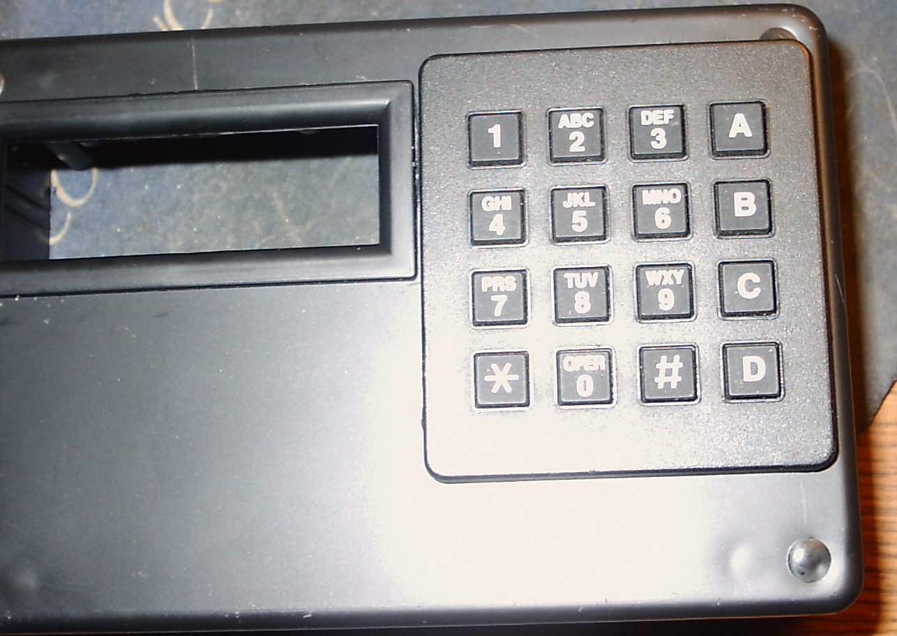
On the front, make an opening for the LCD, allowing room for the optional bezel. Glue the bezel in place. Drill the holes for and mount the keypad, volume (and optional squelch) control(s), the mike jack. Make an opening for the optional CTCSS detect LED if using the MX-465P chip (legacy arrangement). Hot glue the keypad in place.
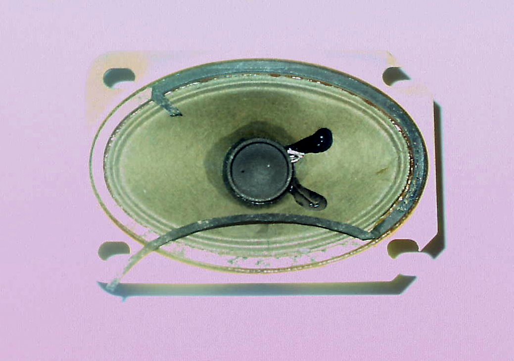
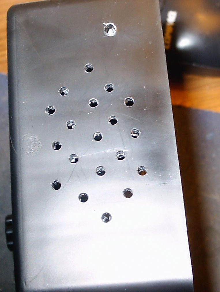
If you have room for a speaker, mount it over to one side after you drill the holes to let the sound out. If there's no room, mount a jack on the rear.
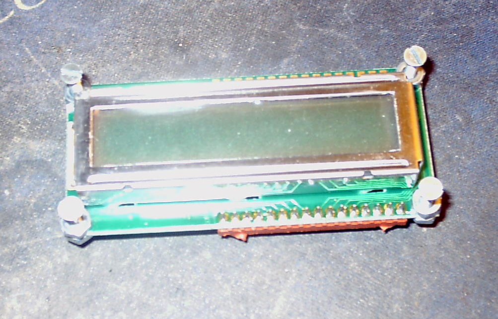
To mount the LCD, connect 4 flat headed screws w/ nuts to the LCD and move it so that the LCD shows cleanly through the opening. Mark the positions of the screws, putting a dab of epoxy or 'crazy glue' in each of the spots. Then, again place the LCD into position and give the epoxy some time to harden. Once done, remove the nuts holding the LCD in place - without disturbing the epoxy joints. You may then go back and liberally coat the flat head mounting screws where they meet the plastic to ensure a really good bond. Let the adhesive cure before proceding.
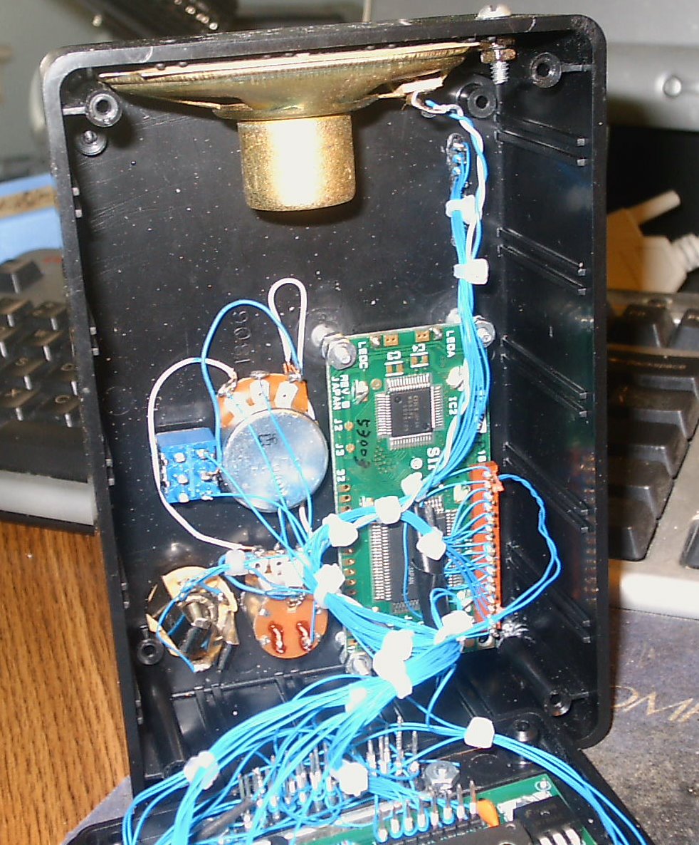
Drill mounting holes in your enclosure for the P/C (control) board, and mount it on the rear of the enclosure. Two screws are needed to secure it to the rear panel. Use the existing hole for the 5 VDC regulator, and use the hole drilled in the opposite corner. Secure the board to the rear panel with screws and lockwashers. Wire it to the DB-25 connector. Make all connections except for the 13 VDC power lead. Make an 'end-to-end' (radio to control head) check.
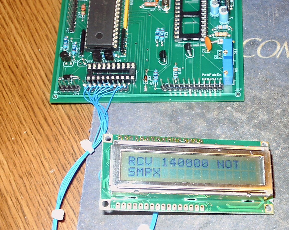
Wire up the LCD to the control board using enough 30 gauge wire to ensure that the back of the control head can be removed with the LCD in place. Once you're certain that everything is connected properly, you may apply power and verify the proper operation of the LCD.
Once done, remove the power. Make the final connections to the keypad, mike jacks, the volume / squelch controls, the ON/OFF switch (rear of the volume control) and to the (optional) CTCSS Detect LED. Secure everything together neatly so that all of the leads to the control board / DB-25 connector run in the same bundle. Then, power it up and verify that it works properly. Before closing the case, make the CTCSS adjustment (R11) with your radio. Once this is done, secure the 4 screws holding the back of the control head and mount it in your chosen location as you see fit.
3. Microphone Requirements
Click here for more information.
DISCLAIMER - - If you follow the steps outlined herein, you do so at your own risk. I cannot, nor will not, be responsible for any possible damage to radio equipment, personal property, to yourself or to others caused by modifications that you may make to the radio as a result of your reading this.
G.E.and the product names Phoenix, Delta, Rangr are trademarks of Ericsson General Electric Mobile Communications.
The M/P controls TRANSMITTING and receiving on many frequencies, suitable for a wide range of HF, VHF and UHF needs. In the USA, TRANSMIT operation requires a license issued by the FCC for the class of operation intended. Amateur radio licensees must maintain strict control over their equipment, preventing unlicensed operation within or outside of the amateur bands.
Copyright 2010 - K3JLS