Host your Web site with iPage!
Automatic
Magnetic Loop Antenna Controller
-
Under Construction -
a) Initial Considerations
This controller has been
designed to automate the control of magnetic loop antennas.
The reader
is encouraged to read through the information on this website to
determine if he or she undertakes this project.
There are several concerns you need to evaluate:
-
The
first has to do with possible adverse effects to people and
animals
caused by the RF fields generated by a magnetic loop antenna.
RF exposure can be intense and possibly harmful in
close proximity to these (and all) transmitting antennas. Please
check the FCC RF Exposure Guidelines and other web
sources to
help you make an informed decision about whether or not a magnetic loop
antenna is right for you and for your family.
- There
is always the possibility
of equipment damage, especially when
connecting something to equipment not expressly
designed for it. (Even connecting 'compatible'
equipment items has been known to cause problems). Today's
electronic equipment is not 'cheap' and can be damaged
in a number of ways, viz: by electro-static discharge, by lightning and
by transmitting with no antenna attached, or into an antenna
with a high SWR.
- The
controller described herein attempts to facilitate the safe and
automatic tuning of a mag loop antenna by reducing the output power to
an acceptable level via ALC control so the RF output circuitry
will not be damaged when the line SWR is highr.
The
prototype version works perfectly well with my IC-746, and I believe
that it will work just as well on other similar, mid-range radios.
- But
I cannot, and will not be responsible for any personal damage and / or
damage to your equipment should you undertake this project.
b) Magnetic Loop Antenna
Experiments
For
several years now I have been experimenting with
Magnetic Loop Antennas at this QTH. In
the beginning, I tried octagonal 3/4" copper loops with homebrew
‘trombone’
capacitors wrapped in Teflon tape and driven by a surplus screwdriver
motor. While they worked OK, they were a real
nuisance to peak after QSY’ing.
After this, I built a similar loop that used an MFJ
butterfly capacitor, driven by the very same motor that MFJ
uses in
their magloops. The motor was controlled by a microprocessor
and an SWR bridge designed to automatically sense resonance.
This semi-automated approach worked better, but experienced difficulty
hitting the ‘sweet spot’ as the
analog motor – controlled by a M/P generated PWM
signal –
would often drift past resonance, and the controller would keep hunting
back
and forth over it. Operation
was not always consistent.
Finally, at the suggestion of Byron
– WA8LCZ – I used a
stepper motor in conjunction with the MFJ butterfly capacitor and
programmed
the controller to automatically hunt for resonance.
The microprocessor driven controller – when activated
– will perform the following steps:
- Apply ALC
voltage to the transmitter to save the final amplifier transistors
during tune
up,
- Key the
transmitter / transceiver in either the CW (key) or SSB (PTT) mode),
- Apply a
1Khz. tone to the microphone input to provide a signal source (so there’s no
need to switch modes while tuning),
- Automatically
rotate the capacitor to resonance, and then
release
the
whole connection, with a resonant antenna, ready for use.
If desired, the capacitor can be rotated manually, at either
slow or fast speed. Resonance will be noted by
the marked
increase in background noise.
The stepper motor approach has proven itself to be much more accurate
than the analog motor, for the following reasons:
- Predictable and more accurate control,
- No brush generated noises when tuning in the receive mode,
- No 'drifting' in the presence of RF when finally tuned, and
- Higher torque for moving 'heavier' capacitors.
The
current design works
best with butterfly capacitors as
it’s very difficult for
the controller to determine in which direction to rotate the capacitor
unless the
detected SWR happens to fall within the capture range of the
Directional
Coupler (described later). If the SWR is
4:1 or less, then the controller will move the stepper in one direction
while
noting any increase or decrease in SWR, adjusting
accordingly.
However, if the SWR is higher, then the
controller will keep moving in the initial direction while ‘watching’
for a
decrease in SWR. Once found, it will ‘zero
in’.
With a butterfly capacitor (rotatable over 360
degrees), this is no problem. I’m
still trying to develop an efficient remote phase detector to ‘tell’
the
controller in which direction to move the capacitor. The
best I can offer for
those wishing
to use a vacuum variable, for example, is a ‘limit switch’ type of
sensor at
the capacitor itself which, when activated, will alert the controller
to change
direction. The
stepper motor design is more complex than conventional analog motors
(as used
in the MFJ Magnetic Loop design and in homebrew loops)
where the end of tuning travel interrupts the current feeding
the motor
via the limit switch. This
current ‘interruption’
followed by a polarity reversal will not work with a stepper
motor as
the controller needs to reverse the stepping sequence.
2.
Purpose
This website will not go into any exhaustive details about
how to build magnetic loop antennas as there are many excellent sites
written by authors much more experienced than me. For anyone
who is interested, however, I will briefly describe the magnetic loop
I'm currently using with the intelligent
controller should anyone care to replicate this design.
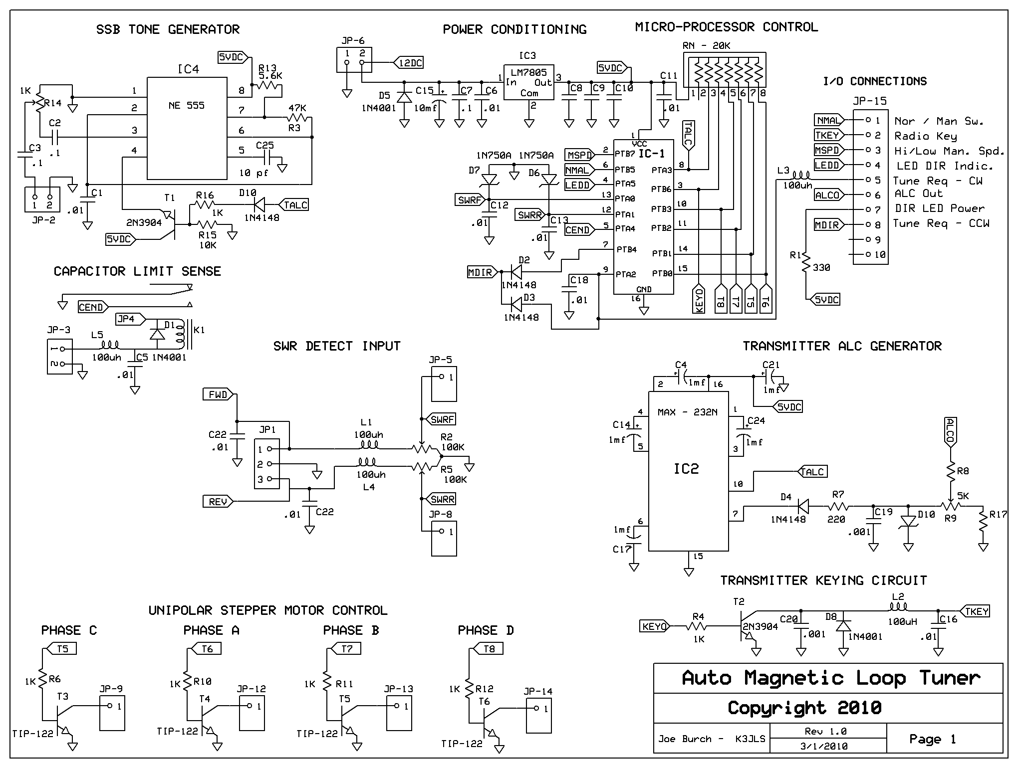
3. How The
Controller Works - View
the Schematic Diagram
The controller itself is driven by a
Motorola MC68HC908QY4
flash programmable microprocessor (M/P).
The controller has been programmed to move the UNIPOLAR
stepper motor in either the forward or reverse directions using the half-step
mode. The simplicity of this approach is that no additional
stepper motor interface chips (aside
from the 4 TIP-122's needed to drive the motor itself) are
required.
All the "stepping' code is within the M/P.
However, one
potential drawback is that the microstepping
offered by the other more
complex driving arrangements
(with special purpose chips and software overhead) is not
available in this design. Rather, the builder
may have to use an
external reduction gear at the capacitor itself to achieve the degree
of resolution to automatically tune the loop close to 1:1 SWR.
I used a reduction gear in my loop.
There are just 3 switches on
the
controller, and 2 (normally open) push buttons.
- The first
DPDT switch (ON / OFF)
turns on the power to the controller and to the
stepper motor.
- The second SPST switch is the mode (AUTO
/ MAN), and the
- Third SPST switch controls the speed (FAST / SLOW)
when in the MAN mode
only. This switch has no function in the AUTO mode
as the stepper motor
speed and direction
of rotation is controlled
autonomously
by the M/P.
- The UP
and DOWN
push buttons, when
pressed in the AUTO
mode will start a tuning cycle by keying the radio,
etc. In the MAN
mode, they simply rotate the motor.
On power up, the M/P initializes and
goes to the WAIT mode. When in the AUTO mode and when
either of the UP
or DOWN
Tune buttoms are pushed, the M/P will apply
ALC voltage, activate the SSB tuning tone and then key the transmitter.
If, after 250 ms, no RF is detected, the M/P will release
everything.
If RF is detected, the M/P
will examine the SWR provided by the external Directional Coupler or
SWR Bridge.
If the SWR is 4:1 or less, the M/P will step the motor along
for a couple of steps and then re-examine the SWR. If found
to be less, the M/P will keep moving the motor in the same direction,
hunting for resonance. If the SWR has increased, the M/P will
reverse the direction and keep hunting. A front panel LED
shows motor direction.
When resonance has been found, the M/P
will release. The user has an additional 2 seconds to use
either the UP
or DOWN
buttons to fine tune the loop if the absolute 1:1
point has not been found. Sometimes this happens.
In the MAN mode, the M/P
will work in
either the FAST
or SLOW
modes. The FAST
mode is useful in
finding near resonance by listening to the receiver noise / or actual
signal. In the FAST
mode, the transmitter is not
keyed.
The
SLOW mode is useful for fine tuning
the transmitter as the M/P will first apply ALC, key the transmitter
(etc) for as long as either the UP
or DOWN
buttons are depressed.
So, for example, an amateur could use just the MAN mode to
fine tune a mag loop antenna without resorting to the AUTO
approach.
4.
Construction of the Intelligent Controller - Parts
Inventory
The ideal construction method is a
printed circuit board (PCB).
Thus far, I have designed a PCB
(about 3.5 x 4 ''), but have
yet to submit it to the PCB manufacturing facility, mainly
because:
- I'm personally happy with my 'breadboarded'
design, and
because
- subsequent demand for any P/C boards is uncertain at this
point.
Please Note:
The breadboarded design picture shown on this website is more complex
than necessary as the board mounted switches and the extra components
are needed for the development phase and to program the M/P from a
personal computer.
If the amateur community expresses any
interest in P/C boards, then I'll undertake its manufacturing
so long as all of the per board manufacturing and shipping costs are
covered. I've had boards made before for other projects and
the per board cost usually came out in the $18 / $22 range.
For fully
automatic operation, the SWR sensing is required.
The primary benefit of remoting an SWR sensor from the
controller itself is
that, in addition to removing RF from the M/P, the interconnection
coaxial cables (from the transmitter to the sensing device and from the
sensing device to the loop itself can be placed on the floor, away from
the
equipment desk and connected to the controller with a shielded 2
conductor cable. The controller itself -
while small - can be placed in a convenient space on the desk with the
UP / DOWN
push buttons mounted in a small plastic enclosure
anywhere on
the desk. Taking this one step further, the AUTO / NORM and FAST / SLOW
switches could also be mounted in the same enclosure.
Two
types of remote SWR sensors will work with the
loop controller if
automatic tuning is desired. The first is a directional
coupler,
and the second is a type of SWR Bridge. I have personally
used
both. The directional coupler was purchased from W8DIZ
and
modified with higher wattage 51 ohm resistors. It comes
complete
with a P/C board, requires no adjstments and is easily built /
installed.
The SWR Bridge type uses a single bi-filar wound toroid, a variable
capacitor and a handhul of parts, is constructed on a small piece of
(Radio
Shack) perf board and requires a single (null tune) adjustment.
b) Manual
Operation
If only manual operation is required,
then the remote directional coupler is not required.
Furthermore, other features may be omitted, like the SSB
transmit Tone, ALC provision, etc, etc by not installing the
components shown on the functional schematic and in the 'Chinese menu'
parts listing.
c)
Breadboarding the Loop Controller Circuit
Any builder experienced in breadboarding
construction techniques could whip up a suitable controller using the
parts shown on the attachment (some
of which may readily be found in his / her junkbox).
I can provide a programmed M/P to complete
the package.
5.
Choice of a Suitable Stepper Motor
a) UNIPOLAR
with a Small Step Size and (Possibly) a Reduction Gear
This is perhaps the most challenging
part of the process. Ideally, you should look for a UNIPOLAR
motor (BI-POLAR will NOT work
in this design) with a small step size -
say .9 degree. This means that the motor will have 360/.9 =
400 steps per revolution if used in the full step mode. If
used in the half step mode, then each step will be .45 degree, and the
motor will have 360/.45 = 800 steps per revolution.
When fine tuning
a mag loop, you need the finest resolution possible to come
close to a 1:1 SWR. While 800 steps per revolution
might be enough for the tuning of a vacuum variable capacitor, I didn't
think that it would be fine enough for a butterfly capacitor which goes
from min to max capacity in 90 degrees, or in 200 steps in the
half-step mode. So, when mounting the stepper motor on the
capacitor, I interposed a 10:1 Jackson Brothers reduction drive and it
works like a charm with my 20 foot, octagonal, .5 inch copper loop.
I'll try to provide an XCEL spreadsheet to better describe
these requirements.
b) Low
Current Drive
When looking for stepper motors, I
'lucked out' when searching the All Electronics website.
I found a NEMA 17 motor with a .9 degree full step that
required just 450 ma per phase (you use both phases when half-stepping)
- nicely satisfied by a 12 VDC supply. So, I use
a 1 amp Radio Shack "wall wart" supply to power both the controller and
the stepper motors together. In normal operation, neither the
supply nor the TIP-122's get warm and no heat sinking is required.
Later on you'll find some additional reading /
research material on stepper motors.
6.
Building the Magnetic Loop Antenna
Since every ham has his or her own
construction methods, I'll show you 'mine' if you promise not to laugh
(hihi).
a) Copper Loop Construction
First, I constructed an octagonal
magnetic loop antenna using 20 feet of copper tubing and 8 - 45 degree
elbows purchased at Home Depot. I cut the tubing
into equal lengths, cleaned the joints and soldered it up.
Nothing really
special here, right??
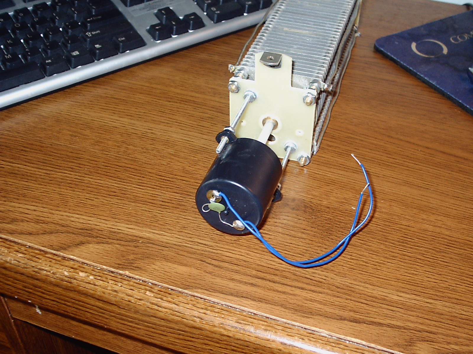
Next, I mounted the stepper motor onto a
piece
of spare aluminum that I had from a small Radio Shack project
box. I used 3 of these sheets, one to mount the motor itself,
one to hold the reduction gear, and the last one to bolt the whole
thing to the MFJ variable capacitor.
Here's how the capacitor assembly looks all
bolted together.
Next, the 'whole thing' is placed within
a 4" PVC drainpipe which will
remder it waterproof when the top is placed on it, as
shown here.
Note: There is a 4
inch cut in the top member of the octagon to allow connection to the
variable capacitor.
That's Home Depot 5 conductor thermostat
cable hooked to the stepper
motor. Finally, the capacitor assembly is mounted on the top
of a PVC mast, and the top copper member is opened up so that each end
of the loop may be connected to the top of the capacitor with heavy
gauge wire. Not very pretty, but it is waterproof
and it does
work well.
b) Feeding The Loop - A Toroid Seems Better
For feeding the loop, I've used both wire and Faraday Loops.
By
adjusting the coupling loop, it's possible to get a very low SWR on
several ham bands (e.g. 40, 30 and 20 meters with a 20 foot loop).
Recently, I replaced the wire coupling loops with an FT
240-43
toroidal core. The toroid is placed one the lower leg of the
loop, shimmed and centered in place with a short length of PVC pipe.
The coax from the transmitter terminates in a 3 turn link (of
#14
enameled wire) wound thru the toroid (see picture).
In my experience, this feeding method is preferable as the
loop
seems somewhat quieter in the receive mode and presents a very near 1:1
match without any manipulation (as
was common with the wire-type coupling loops).
7. Testing It Out - Verify the Stepper Motor
Operation First
a)
Identifying the Stepper Motor Leads
If you decide to 'encapsulate' your capacitor / reduction gear /
stepper motor assembly in a waterproof container, verify
its operation with your controller before enclosing it.
Accordingly, connect it up to your controller, referring to
the
manufacturer's data (if any).
Your surplus
UNIPOLAR stepper motor may have 5 leads, but will generally have 6 or
even 8 wires. The wires for the 6 and 8 lead varieties exit
the
motor in either 3 or 4 lead 'bundles', respectively. UNIPOLAR
steppers have 2 coils per stator pole.
- In the 8 lead motor,
the two leads from the two coils from both stators
emerge from the motor.
- In the 6 lead motor,
the two coils on each stator pole are joined (opposite sense)
together before they emerge from the motor.
- In the 5 lead motor,
each of the two joined wires are themselves joined before
they leave the motor.
Please check out the
following information
to determine how to connect the power, and the A, B, C and D leads to
your magnetic loop controller. As long as you have correctly
identified the power lead(s), and the respective stator pairs, the
worst that can happen when they are connected to the controller is for
the motor to 'quiver' when either the UP or Down buttons are depressed
in the Manual mode.
Once you have the motor
'poled up' correctly, ensure that there is no binding of either the
capacitor or the reduction gear (if used) when operating in the FAST
mode.
b) Interfacing with the Stepper Motor
Connect the coax directly to your magnetic loop antenna. Do
not
connect the KEY / PTT, ALC or SSB tone leads at this point.
Then,
in any amateur segment for which your loop is designed to
operate, peak up the received signal in the MANual mode, FAST speed by
pushing either the UP
or DOWN
buttons. If you can, the motor is working
properly. Verify that the REV LED changes state when the
direction of rotation is changed.
Place the radio in the CW mode, reduce the
RF power as low as it will go, switch the controller to the SLOW mode, depress
your key and watch the SWR bridge as you hit either the UP or DOWN
button to reduce the SWR to its lowest point. If you see a
dip,
but not close to 1:1 and if you're using a wire loop / Faraday Shield,
remove the RF and adjust the position of the loop. Then, try
it
again. If your wire coupling loop is 1/5th the size of the
main
loop, you should be able to get very close to 1:1 by adjusting the
coupling loop shape (i.e. 'squashing' it a bit from a circle to
somewhat of an oval).
You may now
consider your loop adjusted. If desired, you can use the
controller as it is, in the purely manual mode - it works pretty well.
You may also decide to activate
the ALC and PTT / KEY circuits to save you the time and effort of
changing modes / reducing power when tuning up the loop. But,
if
you want totally automatic operation, then you'll have to build a
suitable RF sensing arrangement, as shown below.
c) Testing the CW Keying Interface
Connect the KEY leads from the
controller to your radio. If you are using an external keyer, you
may have to 'tap in' on the output side of the keyer.
Place the radio in the CW mode, reduce the
RF power as low as it will go, switch the controller to the MAN / SLOW
modes, depress either the
UP or DOWN
button and verify that the radio keys and outputs a low RF level.
Release the button and verify that the radio stops
transmitting,
By watching the SWR meter, 'toggle' either the UP or DOWN button (as
required) to achieve a low SWR and then release the button.
Note: If you use CW
most often, if you don't mind adjusting the RF power, and if you don't
need automatic operation, you're done!
c) Testing the SSB PTT Interface
Connect the KEY leads from the
controller to your radio. Using a shielded cable,
connect the TONE
lead (and ground) to the SSB mike input. Most of the newer
radios
provide a rear connection for this purpose and make these leads
available in a DIN jack. If not, then you'll have to make the
connection at the microphone plug. Place the radio in the SSB
mode, switch
any compression off, and switch the controller into the MAN / SLOW modes.
Turn down your radio's RF power to its
lowest level. Next, switch the controller to the MAN / SLOW
modes, depress either the
UP or DOWN
button and verify that the radio keys the PTT function.
Adjust the SSB
TONE LEVEL
control in the controller to produce a few watts of RF output with your
mike gain set in the normal operating position, and verify that you can
tune the loop through resonance. When done, release the
button..
Note: you
don't mind adjusting the RF power when tuning up, and if you don't need
automatic operation, you're done!
d) Testing the ALC Interface
Note: This is an
important test as connecting an improper ALC voltate to your radio may
damage it.
Don't connect the ALC lead to your radio yet. Remove the
magnetic loop antenna and connect a dummy in its place. Set
the CW mode. Set the controller to the MAN / SLOW modes,
and connect your voltmeter to controller's ALC output lead and ground.
Set
the voltmeter to read a negative
voltage.
Hold down either the UP or DOWN button and
check the negative voltage produced. Vary the ALC LEVEL ADJ
control (R9) to both extremes, noting the maximum and minimum voltage
levels. If the maximum negative ALC voltage produced exceeds
what
your radio can tolerate (check your owner's manual), then you'll have
to change Zener diode D10 to a lesser value.........
If the ALC voltage level does not exceed the
limit defined in your operator's manual, then power down both the radio
and the loop controller, and connect the ALC line and ground to your
radio. Power up the radio and then the loop controller. Be
sure that the dummy load is still connected.
Put the radio in the CW mode, operate
the MAN / SLOW
switches on the controller, and depress either the UP or DOWN
button while noting the RF power delivered to the dummy load.
Turn up the power on the radio to max output and adjust R9
until
the transmitter's power drops down to its lowest level, around 1 or 2
watts. Then, release the button.
If you
do not see the need for automatic loop antenna tuning, and are content
to tune the loop manually (in the FAST
mode for maximum noise and then in the SLOW mode for fine
SWR tuning), you are finished.
If not, move on to the next step which is connecting and aligning the
remote directional coupler or SWR bridge.
9. Connecting and Aligning the SWR
Sensor
Two types of RF sensing arrangements can be used, either a fixed-tuned Directional
Coupler, or a more
conventional SWR
Bridge type of arrangement, which requires a simple
'null' adjustment. These sensors will send low level DC
(FWD and REV) signals to the loop controller board which, in turn, will
compute the actual SWR and move the motor / capacitor to resonance.
a) Building,
Adjusting and Using the Remote SWR Sensors
- Construct
either unit from the schematics shown
and mount it in a suitable
enclosure. If building the W8DIZ coupler, replace the
supplied
1/4 watt 51 ohm resistors with the 3 watt units shown in the parts
list. You'll
need the extra wattage to handle 100 watts out. Everything else should
hold up, at least the components in mine do.
There's no need to install the variable trimming resistors; just be
sure to place jumpers so that the DC signals
arrive at the proper output point. Alternatively, you may install
the trimmers and place them in the position of least resistance to the
output.
- Identify the SO-239 connectors for the transmitter
(IN)
& for the antenna (OUT),
and make the FWD
and REV
connections to the output 3 wire jack.
- Connect your transmitter (with an external SWR bridge, if
required) to the IN
jack and a 50
ohm dummy load to the OUT
jack. Verify that you have continuity thru
the coupler by transmitting at low power. (say, 10 watts).
- If
you are building the SWR Bridge sensor, connect the voltmeter between
JP-8 (REV)
on the controller board and ground. Then, carefully
adjust the null capacitor for as low a reading as possible.
It
should dip close to 0.0 volts (0.1 volt is OK).
- Next, connect your voltmeter between JP-5 (FWD) on the
P/C board and ground.
- Gradually
increase the output power to the 100 watt level. Check the
remote
sensor for any signs of overheating. Then, cut the power.
- Quickly key the transmitter again and adjust R2 (FWD) so
that JP-5
reads 4.0 volts. Once done, cut the power.
- Swap
the connections at the remote sensing device. The
transmitter is now feeding the OUT jack and the dummy load is connected
to the IN jack.
- Connect your voltmeter between JP-8 (REV) and
ground.
- Quickly
apply 100 watts of transmitter power and adjust R5 (REV) so that
JP-8
reads exactly the same as the previous reading. Then cut the power.
- Restore the
connections on the directional coupler to their original state.
10. Using the Automatic Mag Loop
Controller
a) Automatic Tuning a
Butterfly Capacitor
If you are using the controller with a butterfly antenna that's free to
rotate 360 degrees, tuning up is very easy. Just
push either the UP
or the DOWN
buttons with the controller in the AUTOmatic
mode and the tuner will do its thing, provided, of course,
your antenna has been proven to resonate in the band you are
using. When the controller stops tuning (and your
radio returns to the receive mode), you have an additional 2 seconds to
'fine tune' your antenna with either the UP or the DOWN buttons.
If you wait
longer than 2 seconds, the controller will go into another automatic
cycle.
b) Manual
Tuning a Butterfly Capacitor
You can tune your loop in the MANual mode using
either the FAST
or SLOW
buttons. Pressing the FAST
button simply moves the stepper motor in the fast mode - without keying
the transmitter. This is a useful way to peak your received
signals while tuning around the band, while SWL'ing, etc.
The MANual
SLOW mode
will key the transmitter, apply ALC,
generate an SSB
tone, etc. and is useful for fine tuning your antenna to the point of
the lowest SWR.
c) Automatic
Tuning a Vacuum Variable or Similar Capacitor
....more to follow...
11. Interesting Magnetic Loop
Antenna Websites and Related Articles