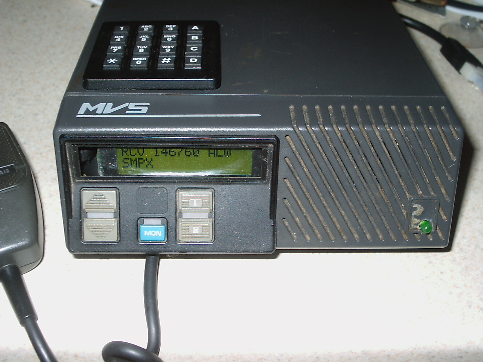
Upgrading GE MVS VHF, UHF Dash Mount Radios
Here are the step-by-step instructions to convert GE MVS
radios for use on 2 meters, for 440, and for GMRS. Please read through all of these
instructions before modifying your radio.
General Radio Information
Conversion Considerations
Conversion Steps
Removing the Front Cap
Removing the LCD
Installing a New LCD
Identifying the Mike PTT Lead
Reinstalling the Front Cap
Drilling Mounting Holes for the P/C Board
Making Logic Board Connections
Making RF Board Connections
Mounting the P/C Board
P/C Board Connections
Keypad Connections
CTCSS Connections
Final Testing
Transmitting CTCSS Tones
Removing the Beep Tones
Conclusion
a) About the MVS VHF and UHF Radios
There are many MVS radios currently advertised on e-Bay. The 2 channel
radio is especially popular and inexpensive, mainly because there is little commercial demand
for 2 channel radios.
These are high quality commercial units that will
provide long lasting amateur radio service. When upgraded with the combined M/P and CTCSS
controller, the rugged and plentiful MVS will provide superb 'frequency agile' amateur service.
Furthermore, the MVS is small, contains its own speaker, draws
only 8 AMPS from a 12 volt automobile battery, and can be mounted almost anywhere at home
or in the car / camper, etc. It makes use of integrated components (like an RF Power Amplifier
'brick'), it contains two microprocessors, and is probably the most state-of-the art radio
available today for amateur conversion possibilities.
It consists of the following plug-in modules:
the Front Cap assembly, the RF and PA Boards, the Audio Board, the Logic and System Boards.
b) General Conversion
Information - How It Works
You may convert your MVS radio in one two ways. The
easiest approach is to install the M/P board and LCD unit within the radio
itself, 'remoting' the keypad and off / on pushbutton in a small plastic box
which is easily viewed by - and accessible to - the driver. This approach is
probably the safest as the driver need not look under the dashboard when
attempting to QSY. Furthermore, this is the more aesthetic approach as the new
LCD will fit in the space vacated by the 'stock' LCD unit.
Alternatively, you may mount the LCD, M/P, keypad and
circuit board in a separate enclosure.
- Transmit Frequency Out of Allowable
Amateur Range
If the transmit frequency is out of range, the M/P will
display BAND, and will not attempt to cycle the MVS through the transmit
state. Amateurs living outside of the United States may enter a
security code to do so.
c) Conversion Steps - MVS Bottom Connections - Integrated Schematic
Important Note: As MVS
radios use CMOS technology, follow safe CMOS handling procedures.
Never use a soldering gun.
Use a 15 to 30 watt (grounded) soldering
iron.
Also Note: Before touching any
of the internal components, first temporarily ground yourself by touching a
known good ground, thus draining away any static electricity potential.
If you have a wrist strap, use it.
First - verify that the radio works on transmit and receive,
by using a dummy load. Check the duration of the Transmit Timer.
If its time is LESS than you are likely to use when transmitting on the amateur bands,
then you will have to get the radio reprogrammed BEFORE attempting any modifications.
Any commercial radio shop should be able to lengthen the timer to the required interval.
If you like, I can do it for you for a nominal charge.
The best bet is to totally disable it. This should be done on ALL available channels.
Construct the combined M/P and CTCSS circuit board, install the
appropriate diodes and temporarily connect the LCD to ensure that it is working
properly BEFORE attempting to install it in the bottom of radio itself. You'll need to connect
it to a +12VDC source for these checks.
Remove the TOP cover from the radio:
Insert a small screwdriver under one side of the top cover and GENTLY pry the side of the
cover away from the frame - releasing the locking tab.Using the screwdriver, press in on
the tabs on the rear of the radio and release the locking tabs.
Insert the screwdriver under the other side of the radio top cover, releasing the remaining
locking tab, and remove the cover from the radio. While the cover itself is plastic, please note the
generous use of copper sheet shielding material.
Remove the BOTTOM cover from the radio - Remove the two screws holding the
bottom cover to the radio (one of these screws is used for the microphone
strain release). Then, remove the bottom cover. (You'll need either several TORX screwdrivers
or a set of allen wrenches).
d) Removing the Front Cap - Partial Disassembled View
If you would like to use an EXTERNAL LCD, the existing internal LCD and power switch will still
function. The LCD will display the setting of the Volume Control, the Busy Idle
status of the frequency in use and Transmit status of the radio. However, a
separate enclosure will be needed for the LCD.
you will need to remove the front (control) panel assembly
which is also called the 'FRONT CAP. The Front Cap assembly contains the 3 watt audio
amplifier, the LCD, Power Switch, Digital Volume Control, Speaker, Voltage regulators,
Monitor and Scan Controls (if so equipped).
Remove the two screws on either side of the Front Cap and the two screws on the bottom.
Then, carefully slide the Front Cap away from the rest of the radio.
Remove (and store) the two clips that provide a heat sink for the voltage
regulator and audio amplifier mounted on the upper left hand corner of the Front Cap (looking at it from the rear).
Unclip the plug (J801) containing the two orange wires that go to the front panel mounted
speaker.
CAREFULLY unplug the two ribbon cables going to the keypad and to the existing LCD. Use a
small screwdriver to push back the plastic locking clips and then gently separate the plugs
from the circuit board.
Remove the 4 TORX screws holding the circuit board and carefully remove it. Also, remove the
keypad assembly from the front of the Front Cap.
e) Installing the New, 2x16 LCD
Remove (and discard) the existing LCD. It is mounted to the metal frame of the Front
Cap assembly with 3 smaller TORX screws. Next, you will be drilling two holes to mount the
internal LCD.
Remove the metal chassis from the plastic front panel, proper. There are several screws
holding it in place. Don't damage the speaker in the process.
As you'll note, there's a limited amount of space within the front cap in which to install
your 2x16 LCD unit. I had two (surplus) LCD's on hand and only one of them fit in the available
space properly. The OPTREX unit did not readily fit, without some judicious cutting.
A newer $6.00 Seiko unit fit perfectly.
Position your LCD so that it is visible thru the existing front panel bezel. You may have to
cut the panel so that the LCD's rear mounted pins will not contact the panel. This is easily
accomplished with a small hacksaw or 'nibbling' tool as the metal breaks easily.
Make sure that the keypad assembly will close and lock over the newly installed LCD.
There are 14 connections required to interface the LCD unit with the M/P, +5VDC, ground and
contrast - found on the LCD as pins 1 thru 14. Depending on your particular LCD, there may be
two additional pins - 15 and 16 - which are used to provide power to the LCD backlight. If your
LCD has these pins and if you want the backlight feature, you'll need to extend them, as well.
If your LCD has K and A terminals on it, you can make the required backlight connections (and the
82 ohm dropping resistor) right on the LCD board, proper.
Drill the required holes, install the mounting screws, lock washers (etc) and check for proper
alignment. Once correctly positioned, remove it once more and connect the wiring in
such a way that it will not not touch the metal chassis or interfere with the keypad assembly
(You may want to insulate the back panel with some tape).
Use about 16 inches of 30 gauge wire for each lead, securing the whole bundle with a couple of
plastic cable ties. Then, you may permanently re-mount
the LCD.
If you want the CTCSS Tone Detect LED, drill a small hole in the lower
right front panel of the radio in the space occupied by the GE logo. Connect two 16 inch
lengths of 30 gauge wire to the LED and 'crazy glue' it into place. Run these wires in the
same bundle as the LCD leads.
f) Identifying the PTT and RESET Leads
Next, identify the mike PTT lead on the 8 pin connector (J725) into
which the mike plugs on the underside of the radio. It's the pin closest to the microprocessor and
the microprocesor's crystal see sketch. To VERIFY the PROPER pin, use your voltmeter
to find it. Place one lead in pin 2 (it's marked) on the black female DB-9 connector and the other on
pin 10 on J725. Once verified, cut off J725 - pin 10 - as CLOSE as you can to the CIRCUIT BOARD, and then
bend it straight out. Wire wrap a 12 inch length of 30 gauge wire to this lead and tag it as
PTT.
Finally, you'll want to connect the RESET lead to the newly installed M/P. (This
feature will ket your MVS automatically activate the last frequency in use when powered down.
This lead is available on the pin 4 of the front panel microprocessor. An easier
connection point is to the 'pull up' resistor 'feeding'
pin 4, as shown in this picture. Wire wrap a 12 inch length of 30 gauge wire to this lead and tag it as RESET. Run it along with the other leads.
g) Reinstalling the Modified Front Cap
Finally, reassemble everything in the reverse order from which it was disassembled, re-connecting the
keypad ribbon cable. Slide the modified Front Cap back onto the radio, running the LCD and CTCSS Detect
leads to the underside of the unit for future connection to the new P/C board.
h) Drilling Mounting Holes for the P/C Board
On the underside of the radio, remove both the foam rubber 'buffer' (which may or may
not be present). You'll then note three (3) press fitted covers over the circuit boards.
Remove the cover closest to the Radio's front panel and you'll see the underside of the
Logic Board.
Drill holes on the 4 corners of the P/C board and then drill 2 (matching) holes into the cover
of the Logic Board. Do this away from the radio to avoid contamination. Place machine
screws in each of the holes with lockwashers and 'captive' nuts with the screws point upward.
These will be the installation points for the P/C boards (with the captive
nuts serving as 'spacers'). Temporarily attach the P/C board to the Logic Board cover and replace it, taking
care not to unduly bend the tensioned tabs as shown.
Mark the location of the remaining two screw holes on the cover closest to the heat sink, and
then remove both the P/C board and the cover for the Logic Board. Remove the cover on the PA
Board (closest to the heat sink), drill holes at the marked loactions, and install two captive
screws as was done on the Logic Board cover. Remove ALL of the covers.
i) Making Connections to the Logic Board
The Logic Board contains the main microprocessor and memories. Two connections are made
on this board to pin 40 (+5VDC) and pin 8 (COR) of the microprocessor. An easy way to do
this is to use a grounded 15 watt soldering iron and place an additional amount of
solder on pins 8 and 40. Next, remove about 1/4 inch of insulation from a one foot length of 30 gauge wire, bending the bare wire into a
slight loop or 'v'. While reheating pin 40, touch the wire to the pin and it should
readily adhere. When the joint has cooled, verify a secure connections with no adjacent crosses.
Do the same for pin 8. Run the leads along the side of the board so that it will fit in the
space between the cover (once installed) and the frame of the radio. Tag the leads.
j) Making Connections to the RF Board
Between the Logic and RF Boards, there is a 12 pin connector that looks
(when removed) like a centipede. Using a pair of needle nosed pliers, gently remove the
connector by gradually pulling up one end, and then the other - - until free.
At one end of the connector, count in one pin and then remove the 2nd, 3rd and 4th pins by
using a small cutter. An easy way to do this is by bending the pins outward (one by one) and
the cutting them off. This will sever the radio's PLL from the microprocessor on the
Logic Board. Once done, reinstall the connector so that the severed pins are in positions
11, 10 and 9 on the RF Board (Integrated Schematic)
Prepare 3 - 8 inch lengths of #30 gauge wire as was done in step i - for the VCC lead.
Carefully solder them to pins 9 (PLL Enable), 10 (PLL Data), and to pin 11 (PLL Clock) on the
RF Board. They should be in the same positions as the connector leads which you have just
severed. Make sure that they are tagged appropriately, running them to a spot where the
board cover - once installed - will not short them to ground.
k) Mounting the P/C Board
Reinstall the covers on the Logic and P/C Boards, making sure that neither the 12 pin
'centipede' connector nor the VCC and PLL leads are grounded or otherwise disturbed. Before
mounting the P/C board, verify that soldered connections are cut close to the P/C board.
As an additional safeguard against shorts, place tape over the covers where the P/C board is
to be mounted. Double sided carpet tape sticks very well.
Mount the P/C Board using lockwashers and nuts, taking care NOT TO OVERTIGHTEN and crack the
board. To ensure that everything stays tight, you may want to crazy glue the nuts / screw heads.
l) P/C Board Connections
Connect the +5 VDC (VCC) source to the P/C board (JP3 - Pin 1), and nothing else.
Apply power to the radio and verify the presence of +5VDC, using the chassis radio.
(You will nocice that the radio is emitting a series of continuous beeps,
indicating that the PLL is unlocked). Remove power.
Connect ground to the P/C Board on JP3 - Pin 2. Ground is available on Systems Board J905A
Pins 1 or 2. Verify that you have the proper pins by checking for ground between these pins and
the radio chassis.
Connect the PLL Clock, Data and Enable Leads to JP2, pins 1, 2 and 3, respectively.
Connect the the TRANSMT Lead on JP2 - pin 4 to J903 - pin 7.
Connect the COR Lead to JP4 - pin 1.
Connect the LCD leads to JP1 - pins 9 through 16, to JP4 - pins 7 and 8, and to JP8 -
pins 1,2 and 3.
Connect the Mike PTT lead to JP1 - pin 18.
Connect one side of the CTCSS Tone LED (if used) to +5VDC (JP3 - pin 1) and the other to
the CTCSS Tone LED connection (JP7 - pin 1). (The easiest way to determine 'which goes where'
is to temporarily touch them to JP3 pins 1 and 2 first. If the LED does not light, then
reverse the connections. Once the LED lights, make a permanent connection to JP3 - pin 1, with
the remaining wire going to JP7 - pin 1.)
l) Keypad Connections
Next you have to determine what kind of keypad connection you want. You may
either mount the keypad on the top cover (as in the prototype) or in a separate, small
enclosure, say on the dashboard of your car. The choice is yours. If you opt for
a separate enclosure, you should use a shielded DB-9 connection. The 'extra'
lead will also let you mount an ON / OFF switch along with the keypad.
Connect the Keypad Leads to JP1 - pins 1 through 8, as shown on the attached
sketch.
m) CTCSS Connections
Connect the TONE IN lead on JP6 - pin 1 to J903 - pin 11.
On J903 - connect pin 1 to pin 8 - this disables the radio's internal
CTCSS circuitry.
Connect the TONE OUT lead on JP6 - pin 2 to pin #5 of U602 on the Audio Board, using a 30
gauge wire. The Audio Board is on the top side of the radio, and the connection can be made
to this pin without removing the Audio Board itself (see picture).
n) Final Testing - Reference the COMMAND MANUAL
Turn on power to the radio. The front panel switches and LCD should glow.
You will also hear a series (quick burst) of 5 or 6 beeps that indicate that the
PLL synthesizer is unlocked. If you haven't already done so, adjust the LCD Contrast
control (R16) until you have the desired contrast. The first line of the display
should be RCV 140000 NOT.
Connect a suitable antenna, and then depress C followed by 5, causing the radio to
scan the Weather Channels. If there is a NOAA transmitter within receiving range,
you should hear it. While the radio is scanning, you'll hear rapid beeping
which indicates that the PLL is momentarily unlocked. This is because the radio's
existing microprocessor senses the unlocked condition and 'reports' it. Once
the conversion is complete, we'll disable this annoyance.
Try to transmit by pressing the mike PTT switch. The display should show
BAND indicating that the frequency is not within the USA 2 meter band.
Enter your favorite 2 meter (repeater) frequency, set the appropriate offset,
and see if you can bring up the repeater. At this point, the radio should not be
beeping at all. Make a contact and ask for an audio check. If this radio had been
working satisfactorily in commercial service, you should be pleasantly surprised
about the audio quality.
Program the radio for a specific CTCSS tone (say, 100.0) by entering
it on the keypad. Then, take another 2 meter transmitter or H/T e/w CTCSS encode
capabilities, program the same frequency and CTCSS tone and key up the other
radio. The MVS (optional) front panel LED should light indication that the
100.0 Hz. CTCSS tone has been detected.
Again key op your other radio and program the MVS to scan all of the CTCSS
tones. This is (explained in the Command Manual and) done by depressing the
C key twice, followed by the A key. The LCD will display each of the tones until
it 'stops on 100.0 Hz. This is a handy way to determine which CTCSS tone is
being used (e.g. on a repeater) without taking your eyes off the road. When the
tone is 'found', it is automatically programmed into the MVS.
o) Transmitting CTCSS Tones
Program both your 'other' radio and the modified GE MVS to the same frequency and with the
same CTCSS tone. Program the 'other' radio so that its squelch will not open unless the proper
CTCSS tone is received. Transmit with the MVS and adjust R19 until the squelch reliably opens on
your other radio, and remains open as you speak into the MVS mike. If you do not have another
2 meter radio with CTCSS capabilities, then perhaps you could make this adjustment on a nearby
repeater e/w required CTCSS access.
o) Removing the Beep Tones
Details to Follow..............
p) Conclusion
The 2 meter and 440 Mhz GE MVS modifications are relatively easy to accomplish and will provide the user
with a commercial quality amateur rig at relatively low cost. These radios
can be found on e-Bay for usually under $30, or even less.
DISCLAIMER
- - If you follow the steps
outlined herein, you do so at your own risk. I cannot, nor
will not, be responsible for any possible damage to radio equipment, personal
property, to yourself or to others caused by modifications that you may make
to the radio as a result of your reading this.
The M/P
controls TRANSMITTING as well as receiving on many frequencies, suitable for a
wide range of HF, VHF and UHF needs. In the USA, TRANSMIT operation requires a
license issued by the FCC for the class
of operation intended. Amateur radio licensees must maintain
strict control over their equipment, preventing
unlicensed operation within the amateur bands, or
outside of them.
Note: The Terms
Syntor and Syntor X Are Motorola Trademarks
Top
of Page
Copyright 2000 to 2006 - K3JLS