Let's say you're not comfortable rebuilding your Ten-Tec's PTO, or you want SPLIT operation capabilities and don't want to buy a separate VFO (whose PTO may also need rebuilding), or you are reluctant to modify
the 'innards' of your radio with the internal, easy tuning DDS VFO
circuitry. Well, this backlash free controller with its optical
encoder, RIT circuitry,
display lamps and push buttons can all be mounted in a suitable,
'plug-and play' external
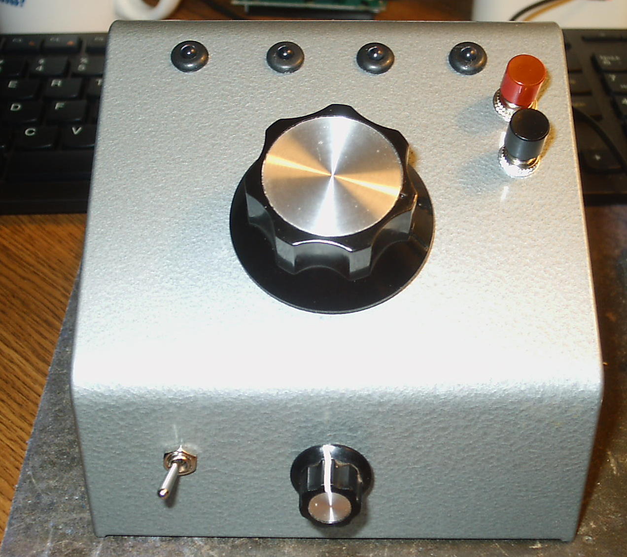
enclosure. Here's one example that has been constructed in a new
BUD sloping cabinet
that was purchased on eBay.
The 4 LEDs across the top depict (left to right) VFO-A, VFO-B, SPLIT and LOCK. The black pushbutton is the multi-purpose signaling button while the red button is an optional button for activating and cancelling the SPLIT function. The toggle switch on the front activates the adjacent RIT function control. This arrangement is sweet and functional. For simplicity's sake, it was decided not to include a power (ON / OFF) switch on the VFO nor any additional circuitry that would allow on-demand switching between the internal and the external VFO's. That is, when the External DDS VFO is connected to either of these radios it will totally control frequency excursions and will be - in and of itself - capable of true SPLIT frequency operation.
The rear of the enclosure has the jacks into which the 13 VDC is provided, the transmit signal is connected and from which the RF output is provided.
1. Interfacing with the Ten-Tec OMNI, Corsair, Delta (etc) Series
For openers, consider the Ten-Tec Omni series. On the right rear panel is a 13 VDC phono plug and two other RCA phono plugs which are jumpered together. These are the connections for an external VFO. The power for the External DDS VFO is taken from the 13 VDC jack, and the 'strap' is emoved from the 2 adjacent plugs which 'disconnects' the internal PTO. The External DDS VFO is then connected to the Remote VFO port.
Another phono plug has to be mounted on the rear panel to which the Omni's transmit lead is connected. This connection is made on the Omni's Control Board, the one that's just below the optional filter board. It's to be placed on the 'R' pin - the third pin from the right (from the side of the radio). It's on the back of the board and can be reached without removing the filter board.
2. Interfacing with the Drake TR7 Series
Interfacing with the Drake TR7 is a bit more involved mainly because an 8 position male Cinch Jones plug - and some additional wiring within the plug - is required. Insofar as the TR7 is concerned, the External DDS VFO mimics the Drake RV7 External VFO with its function switch set so that the RV7 is controlling both the receive and transmit modes. For more information on this topic, you might want to the excellent article written by Floyd Sense - K8AC - on how he elegantly interfaced a much more sophistated DDS VFO to his Drake TR7.
The schematic diagram shows how the connections are made within the RV7 plug. The connections within the plug not only 'power the DDS VFO, but also 'tell' the TR7 that an external VFO will be used for both transmitting and receiving. As soon as the plug is inserted, the External DDS VFO will assume control of the radio. It's really just that simple. An RG-174 coaxial cable connection runs from the plug to the External DDS VFO, and another connection provides 13 VDC and ground. The transmit signal (a ground) from the TR7 is taken from thje PS7 (VOX JacK), and that's allt here is to it. No internal wiring changes have been made within the TR7.
3. Setting It Up - Exercise Caution with the TR7
BEFORE connecting the External DDS VFO to your radio, you should measure the RF voltage produced by its internal PTO at the point where the PTO connects to the radio's internal circuitry. Once this is done, you may connect the External DDS VFO and adjust the VFO Output Control (R5) to provide the same output at the same point. This will compensate for any loss within the coaxial cable.
The Drake TR7's PTO coltage can be neasured by scoping out the PTO point on the underside of the chassis. Mine was 1 volt - peak-to-peak. Accordingly, just connect the External DDS VFO and adjust its output to match what the internal PTO was delivering.
Note: Another unit is currently under construction and will be sold on ebay.
The 4 LEDs across the top depict (left to right) VFO-A, VFO-B, SPLIT and LOCK. The black pushbutton is the multi-purpose signaling button while the red button is an optional button for activating and cancelling the SPLIT function. The toggle switch on the front activates the adjacent RIT function control. This arrangement is sweet and functional. For simplicity's sake, it was decided not to include a power (ON / OFF) switch on the VFO nor any additional circuitry that would allow on-demand switching between the internal and the external VFO's. That is, when the External DDS VFO is connected to either of these radios it will totally control frequency excursions and will be - in and of itself - capable of true SPLIT frequency operation.
Also Note:
The unit currently under construction will include a power switch so
that it can be used for selective transmitting / receiving in
conjunction with the Drake's internal PTO.
The rear of the enclosure has the jacks into which the 13 VDC is provided, the transmit signal is connected and from which the RF output is provided.
1. Interfacing with the Ten-Tec OMNI, Corsair, Delta (etc) Series
For openers, consider the Ten-Tec Omni series. On the right rear panel is a 13 VDC phono plug and two other RCA phono plugs which are jumpered together. These are the connections for an external VFO. The power for the External DDS VFO is taken from the 13 VDC jack, and the 'strap' is emoved from the 2 adjacent plugs which 'disconnects' the internal PTO. The External DDS VFO is then connected to the Remote VFO port.
Another phono plug has to be mounted on the rear panel to which the Omni's transmit lead is connected. This connection is made on the Omni's Control Board, the one that's just below the optional filter board. It's to be placed on the 'R' pin - the third pin from the right (from the side of the radio). It's on the back of the board and can be reached without removing the filter board.
2. Interfacing with the Drake TR7 Series
Interfacing with the Drake TR7 is a bit more involved mainly because an 8 position male Cinch Jones plug - and some additional wiring within the plug - is required. Insofar as the TR7 is concerned, the External DDS VFO mimics the Drake RV7 External VFO with its function switch set so that the RV7 is controlling both the receive and transmit modes. For more information on this topic, you might want to the excellent article written by Floyd Sense - K8AC - on how he elegantly interfaced a much more sophistated DDS VFO to his Drake TR7.
The schematic diagram shows how the connections are made within the RV7 plug. The connections within the plug not only 'power the DDS VFO, but also 'tell' the TR7 that an external VFO will be used for both transmitting and receiving. As soon as the plug is inserted, the External DDS VFO will assume control of the radio. It's really just that simple. An RG-174 coaxial cable connection runs from the plug to the External DDS VFO, and another connection provides 13 VDC and ground. The transmit signal (a ground) from the TR7 is taken from thje PS7 (VOX JacK), and that's allt here is to it. No internal wiring changes have been made within the TR7.
3. Setting It Up - Exercise Caution with the TR7
BEFORE connecting the External DDS VFO to your radio, you should measure the RF voltage produced by its internal PTO at the point where the PTO connects to the radio's internal circuitry. Once this is done, you may connect the External DDS VFO and adjust the VFO Output Control (R5) to provide the same output at the same point. This will compensate for any loss within the coaxial cable.
The Drake TR7's PTO coltage can be neasured by scoping out the PTO point on the underside of the chassis. Mine was 1 volt - peak-to-peak. Accordingly, just connect the External DDS VFO and adjust its output to match what the internal PTO was delivering.
Caution:
When using the External DDS VFO with a Drake TR7, make the power
and RF output connections BEFORE turning the radio on. If you
attempt a power on installation and accidentally ground the power lead
coming from the RV7 connectior, you may either burn out the 100 mh
inductor in the power cord, blow the 5 amp fuse in the TR7 - or both. Replacing either item is a pain-in-the butt.