Heathkit HW-16 - Adding 'Internal' VFO Functionality
PRELIMINARY, INCOMPLETE and SUBJECT TO CHANGE
Caveat:
Before attempting this conversion, know that there are
dangerous and
potentially lethal
voltages involved. Unless
you are absolutely
certain that you know what you are doing and have taken the proper
precautions, don't
perform this work. I cannot be
- nor will be - responsible for any injuries or
damages
incurred as a result
of your reading this website.
This website describes a slightly modified variation of a very
clever design published in Ham Radio magazine. Unfortunately, I was not able to get my conversion working properly as the converted radio did generate some spurious signals................I'm leaving this information on the web (for w a while) should someone else want to complete it.
If you have any doubts about
the modified HW-16 signal 'purity', then you may want to check for
yourself before transmitting. As a precaution, you may use a
narrow bandwidth antenna like a magnetic loop antenna.
I cannot nor will not be held responsible for any spurious signal emissions caused by these modifications.
Introduction
Components and Costs
Modification
Conversion Theory
Steps:
Other Interesting Modifications:
1.
Introduction - HW-16 Construction / Service Manual
The Heathkit HW-16 was a popular Novice rig.
Although I never
owned one (before now), I can remember repairing one for a new ham to
whom I had administered the Novice test back in
Chalfont, Pa in 1972. Since I had previously 'graduated' from
an Eico 720 / 730 combination to an HW-101, I didn't really think that
I'd ever have any use for one of these 'old tube radios'.
However, like many hams
I'm trying
to 'recapture' the thrill of my first CW contacts on my DX-20 back in our Hatboro, Pa home. With this 'quest' in
mind, I have taken to purchasing, repairing and then ultimately
reselling these 'treasures' from the past. The
HW-16 was the next radio to be 'explored'.
I bought this HW-16 on eBay along
with a DX-60
with a
slightly bent front panel. After recapping both rigs with
kits purchased from the Hayseed Hamfest, I decided
to modify the HW-16 with a proper power cord and with an internal VFO as described in the March,
1973 issue of Ham Radio magazine. The DX-60 will be upgraded
later with an internal antenna changeover relay, PTT circuitry and the popular audio modifications.
2.
Modifying the HW-16 - From
Down to Up Conversion
The HW-16 is a tube radio with
separate sensitive / selective receiver and rugged transmitter sharing same robust power
supply. The receiver is VFO
controlled, while the transmitter requires either a separate VFO (like
the VF-1 or HG-10), or individual crystals for the desired frequencies of
operation.
In the March 1973 issue of Ham Radio magazine,
James Takeshima - WB6MZN - described a clever way to allow the HW-16 to utilize its receiver VFO to
control the transmitter frequency. This website article amplifies his efforts by providing a construction technique
if anyone is interested in either following it or improving upon it.
After all, this is what the spirit of amateur radio is all
about, right? Someone once said that we 'all stand upon the shoulders of
those who went before us.'
A few 'tweaks' were made to WB6MZN's design:
- an easier method of mounting the interface board under the chassis,
- a HEXFET based shunt regulator to minimize drift and chirp,
- RF chokes to reduce bothersome RF currents,
- two series resonant 'trap circuits' on the input of the BFO to limit its
strong second harmonic second harmonic (6793 khz), and a
- true RIT circuit.
a) Original Design - Receiver Down Conversion - Transmitter Crystal Controlled
The HW-16 receiver 'down converts'. The incoming signal is mixed with the heterodyne oscillator to produce a frequency in
the 5 Mhz range by passing it through a bandpass coupler (filter) that
removes the extraneous mixing products. The 5 Mhz signal is
then mixed with the tunable VFO signal and then routed through the .5
khz. crystal filter set to 3396 khz. Finally, the desired
signal is 'beat' against the 3396.4 khz BFO to produce audio for the listener.
b) Modified Design - Receiver Down Conversion - Transmitter 'VFO' Up Conversion
The
ingenious WB6MZN improvement
inverts the conversion process when transmitting.
His 'interface'
circuit first combines the BFO and VFO signals (first mixer) and then sent
through the same bandpass filter to remove the undesirable conversion
artifacts.
A signal in the 5 Mhz range remains, tuned by the VFO. This 5 Mhz signal is mixed (second mixer) with
that of the heterodyne oscillator whereafter it is sent through the
transmitters oscillator / driver / PA stages, and then to the antenna and the world.
3.
Conversion Theory - How It Works
With
key down, the HW-16's sole transistor (NTE-102 is the replacement - hihi) turns off and removes the
ground from V2A
(the Heterodyne Mixer), preventing bandpass filter interference.
Interface board transistor QM1 turns
on, supplying power to mixer transistors QM2 and QM3. Mixer
QM3 combines the BFO and VFO signals whose (5 Mhz)output is directed through
the bandpass filter. Mixer QM2 combines the output of mixer
QM3 with the Heterodyne Oscillator, as shown below:
The output of Mixer QM2 will provide the following signals (original
frequencies, sum and differences) with the VFO set to '0' khz:
- 80
Meters: 5545 khz (bandpass), 9045 khz (het osc),
14590 khz (sum), 3500 khz (difference - desired
frequency),
- 40
Meters: 5545 khz (bandpass) , 12545 khz (het osc),
18090 khz (sum), 7000 khz (difference - desired frequency),
- 15
Meters: 5545 khz (bandpass), 26545 khz (het osc),
32090 khz (sum), 21000 khz (difference - desired frequency)
In the original Ham radio article, WB6MZN routed the output
signal through the tuned circuits in the receiver's RF stage as a way
to peak the desired frequency relative to the others present. He
relied on the tuned circuits within the transmitter to further amplify
the desired frequency while attenuating the others. I tried this
technique two different ways and the result was always the same - the
excellent sensitivity of the receiver was reduced to what I would
regard as objectional because the RF amplifier circuit was 'disturbed'.
Now, 40 meter operation works well. However, 80 meters will not produce anything close to full output power.
To solve the 80 meter problem, another parallel resonant tuned
circuit is needed between the Interface Board output and the
transmitter oscillator. Rather than including it on the Interface
Board (I might do this later), I just inserted it into the VFO jack
(more on this in the next update). With it, both 80 and 40 meter
transmissions are proper. While
I could not make any 15 meter tests (weak heterodyne
oscillator crystal), I don't think that there will be any problems with
15 meters since the tuned circuits are far enough apart.
QSK operation is unchanged.
4. Conversion Steps - Check
the Schematic
Every amateur has his or her
own favorite ways to perform such a conversion. Listed
below are the steps that I have taken to perform this conversion on my
HW-16. You are encouraged to make any suggestions or improvements.
a) Preliminary Work
- Ensure your HW-16 is working with proper PA neutralization. Test all
tubes, clean the
moving parts, tube pins, sockets and controls.
Note: As deascribed on the HW-16 Yahoo User's Group, the HW-16 may emit parasitic
signals if the PA is not neutralized properly and if the radio is tuned
for peak RF power alone.
- Replace the electrolytic capacitors as you don't want them
exploding in your face. You may buy these parts from the Hayseed
Hamfest folks. I've bought 'kits' for
3 different radios and they were all high quality parts. This is also a good time to
replace the line power cord with a 3 prong, grounded plug (for safety
and for noise abatement).
- Order the required parts.
A
parts list has been provided for your convenience. I order all my parts from Mouser Electronics.
If you have a well stocked junk box, this will help to reduce the costs which are not that high.
b) Voltage Regulator Installation
- This shunt regulator circuit provides a
constant voltage to the VFO, BFO
and Heterodyne Oscillator tubes to eliminate any 'chirping'
or drifting tendencies. This design itself was
'borrowed' here.
- WB6MZN recommended 'cutting' P/C board traces to
isolate components. Instead, I removed resistors from the top of the P/C boards
and then used under chassis wiring to a terminal strip where the
new resistors would be mounted. In turn, the common feed for
these resistors would be run from the output of the Voltage Regulator
circuit.
Important
Note: Before
starting, remove all receiver tubes lest they be damaged by the heat of
your soldering iron / gun, or when resting the radio on its top.
The corner tube (audio amplifier) is a little larger than the rest and is very
easily damaged - I know.
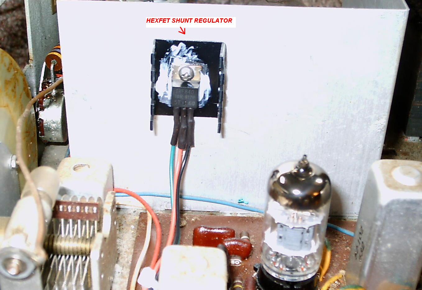
- Determine where you are going to
mount the
IRF840N HEXFET shunt regulator. I mounted mine on the above-the-chassis
shield. You'll need a transistor mounting
kit (which includes the mica insulator), some thermal conductive 'grease', and a small TO-220
type of heat sink.
CAUTION - should
the HEXFET short out to the chassis it (and other
HW-16 components) will be ruined.
- Mount a terminal strip containing
the 3
replacement resistors under the chassis. I placed
them on the shield between the transmitter and the
receiver, but on the receiver side.
The regulator control circuitry is mounted above the chassis. If
I had it to do over again (I might convert another HW-16), I would mount both the
resistor strip and regulator control circuits on the metal shield
below-the-chassis, leaving only the regulator above the chassis. This
would have presented fewer shock hazards. Mull it over
for yourself before
starting.
- Install the resistors and make the
connections
to the respective beneath-the-chassis points. Measure the resistances.
- Mount RM1, the 5.6 K, 5 watt power
resistor
underneath the chassis on a small terminal strip. I used the screw for the pilot lamp. Connect one end of the resistor to the common point of
the terminal strip that feeds the 3 new resistors and the
output of the regulator control circuit. Verify!
- Connect the other end of the 5 watt
resistor to
a source of 310 VDC. A good place is the old R131
connection point.
- Insert all receiver tubes and place your volt meter on the OUTPUT side of the 5 watt
resistor (the side connected to the voltage regulator). Apply
power, watching for any signs of overheating or smoke.
As the tubes warm up you'll note that the voltage begins to
change. Once stabilized, adjust RM3 on the regulator control strip for approximately 220 volts.
It should remain close to this value when either
transmitting or receiving.
Note: If you decide
not to complete the rest of the conversion you may leave the 'improved' radio as
it is.
- Once again, remove all the receiver tubes and
turn the radio
over.
c) Building and Mounting the Interface Board and Additional BFO Series Trap Circuit
- I
used a Radio Shack board (276-149) under V4. Place 3 flat heat (4-40 type hardware)
screws on the unpopulated board, held in place by nuts and washers.
'Tin' the flat ends of each screw and position the
board so that the 3 screws all make contact with the P/C board ground
plane. Then, solder the 'legs' one by one to the foil .
When cooled, remove the nuts and the board. These screws provide a low impedance ground connection.
- Populate
the Interface Board.
The physical construction 'mirrors' the schematic,
with the circuit interface points (A - D - E - C - F - G) running left
to right. There are no .001 voltage isolation capacitors on the board
itself. These 500 volt capacitors are
located right at their HW-16 connection points to keep high voltage away from the board. Once the board is finished, double
check it with your meter and set it aside.
- Important Note:
On 40 meters, the BFO's second harmonic (6793 khz) can 'beat'
against the 7Mhz output and generate spurious signals. A
portion of the 6793 khz signal will also 'sneak' thru and can appear on
the air. For example, with the radio tuned to 7000 khz, the
internal VFO's output signal will mix with the 6793 khz to produce
another an undesirable output on 7207 khz (7000-6793 = 207). So,
a series resonant 'trap' circuit was needed . The first trap circuit
was installed on the Interface Board, but it did not satisfactorily
reduce the BFO's second harmonic, probably because of the lead length
to the Interface Board and the interposition of the coupling capacitor
(CM8). So, a second identical trap circuit was installed right at
V5B, pin 8 - using short leads to both the pin, and to ground. This
seemed to solve the problem. The trap circuit on the Interface Board could probably be removed, but it was retained as a precaution.
- The
trap circuits consist of 11 uH inductors and up to 55 pf in
(adjustable) capacity. For my conversion, I used a 47 pf fixed
value capacitor, .6 - 9 pf 'trimmer' capacitor' and a T50-2 (red
core) powdered iron inductor wound with about 50 turns of small gauge
(dunno exactly) wire, pursuant to these calculations. A grid dip meter is very helpful here.
- Remove R25, a 1K half watt resistor
that
connects the cathode of V2A pin 7 to ground. Connect
one side of the resistor (now
mounted vertically on the underside
of the radio)
to pin 7 of V2A. Connect the other
end to the emitter of Q1, the only transistor used in the HW-16.
This disables V2A when transmitting. Replace R28 with a 270K unit for improved Heterodyne
Oscillator output.
- Run a 6 inch wire from pin 3 of V4
(filament
power) and another 6 inch wire from the base of transistor Q1 - to be connected to the interface board.
Note: Be careful mounting the interface board under V4.
When repeatedly removing / reinstalling the board I accidentally
grounded the filament trace which glowed brilliantly, smoked heavily
and quickly burned up. I used a piece of wire to repair it.
d) Connecting the Interface Board
- On each connection, a 500 volt, .001 blocking capacitor is soldered
directly to the radio connection point and then run back to the
Interface Board with hookup wire. For the tube based
connections, cut one end of the blocking capacitor short so that
it cannot short out to an adjacent tube pin if accidentally 'squashed'.
Place heat shrink tubing over the capacitor's other end and
then make the connections for points C, D, E, F
and G. I used 30 gauge wire wrap wire
which has more
than ample conductivity for these low level AC signals and is very easy
to manipluate.
- Using RG-174 coaxial cable, connect the
interface board's output (Point A) to the VFO input jack Ground
the cable shield at both ends.
- Connect leads C, D, E, F, G, etc. Double check your work when done.
- Turn the radio over and replace all the tubes. Now you are ready to touch up the alignment and test your work.
e) Testing and Alignment
- Adjust the Heterodyne Oscillators first as the transmitter will now be using the
heterodyne oscillator signals in the mixer on the Interface Board.
- set the HW-16's frequenct to 40 meters and connect your dummy load.
- set the new front panel switch for internal VFO operation.
- key the radio and listen for a 6793 khz signal on your station
receiver. Null it out (as best you can) by adjusting both trimmer
capacitors (i.e, CM12 and CM14), one after the other.
- tune the 'new' VFO for approximately 7025 khz and make the
adjustments, per the service manual, for 40 meters, 15 meters and then for 80 meters.
- If you have previously
neutralized the final amplifier, you should get a nice PA current 'dip'
at resonance with a coincident output power peak.
- Using
a second receiver, check for any undesirable birdies of sufficient
amplitiue that they might cause interference, either inside or outside
of the amateur band.
f) Adding RIT