Digital Frequency Displays for the Ten-Tec
Century 21 Analog Transceiver
CAUTION
- When connected to the 120 volt AC
line, there is
always the possibility
of receiving a life
threatening shock.
If you have never worked on 'live' equipment and / or if you
don't think you are able to complete the modification safely, please
do not attempt it. I
will not be responsible for any accidents occurring as a
result of your reading this web page.
Before doing anything, read over these instructions.
Analog Century 21 - Service Manual
Digital
Century 21 - Service Manual
1.
Introduction
Neil Hecht founded the Almost All Digital
Equipment (AADE) enterprise, and he unfortunately passed away last year. You are
encouraged to view his preserved site on the internet Wayback Machine.
As I
had constructed several of his DFD2 units and found them quite well done, I
was disappointed that I could not order other units.
So, I developed both the hardware and software to replicate his
custom DFD-2 for the Century 21 transceiver.
I designed and built this unit for my own needs, but
I
will make a limited number bare-bones boards and pre-programmed PIC processors
available for experienced homebrewers. When these boards are gone - they're gone, and neither will the code be made available.
2.
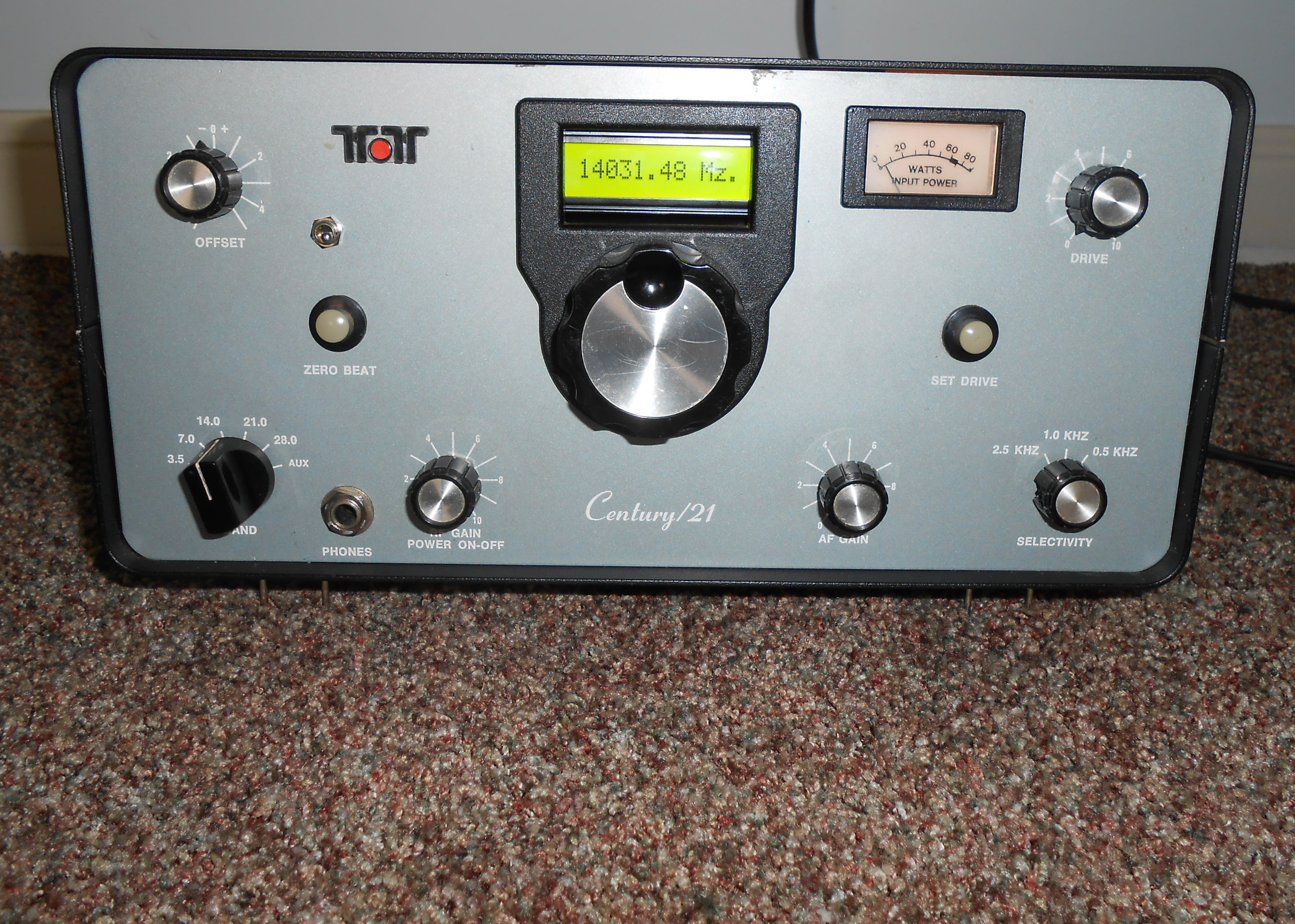
The Century 21 Radio
The Century 21 CW only transceiver was first introduced in the late
1970's. The radio is equipped with a rugged internal power
supply and has a circuit breaker on the power ON / OFF switch to
protect the final amplifier transistors in the case of an SWR mismatch.
It works on the 80, 40, 20, 15 and 10 meter (optional crystals)
bands in the CW
portion. Aside from an infrequent rebuilding of the PTO, it's
a virtually trouble free, fun radio.
For operation well
within a frequency band segment, the
Century 21's analog frequency display is adequate.
However, to
work near the band edges (e.g. to
catch that
elusive DX on 40 meters) or to be exactly on the recognized QRP
frequencies, some form of
frequency calibration is required. While the dial displays the
frequency in 5 Khz increments, and while the PTO design is very well
done, the PTO is not linear throughout its range.
Note: According to Ten-Tec, it's possible
to end up with a plus or minus 3 Khz (or more) deviation on one band,
even if the radio has been precisely adjusted.
I wanted to make the display autonomous by letting the HFO frequency determine whether to ADD or
SUBtract the PTO / VFO frequency. However, this was not possible as the 9.0
Mhz HFO crystal is used for both 80 and 20 meters.
So, some form switching is required. There are no
spare contacts on the Century 21's bandswitch to accomplish this
(unlike in the Omni series - and in the Digital Century 21 - where a
separate bandswitch waver is provided for the display's UP / DOWN
switching).
Note: So, a miniature SPST (BAND
SELECT) switch is mounted on
the remote display itself to accomplish this purpose, and is connected
to the SELECT pins on the PCB.
3. Upgrading the Century 21
Transceiver
I 'tweaked' the PIC code in the Heathkit
DFD-2 Clone for the Century 21. The rest of this website
describes how to add either an external, or internal DFD-2 clone to the
Century 21. For either upgrade, you'll need to assemble an
interface board, described below:
Note: This is also an opportune time
to determine if you will add an internal keyer to your Century 21, as a
three conductor jack might be your best bet. This will also solve
the raspy sidetone
problem.
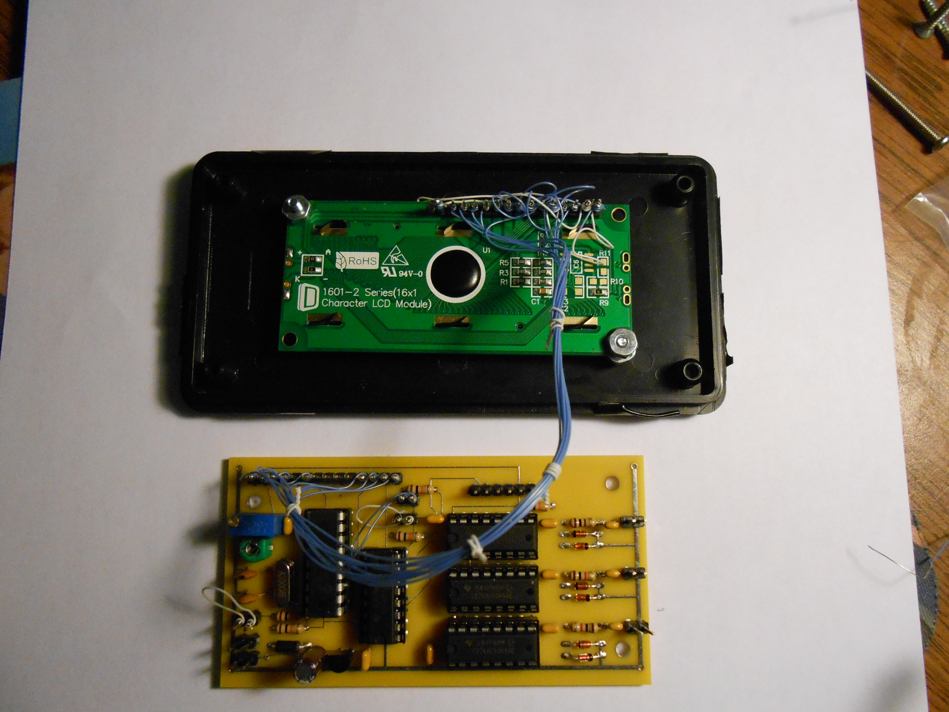
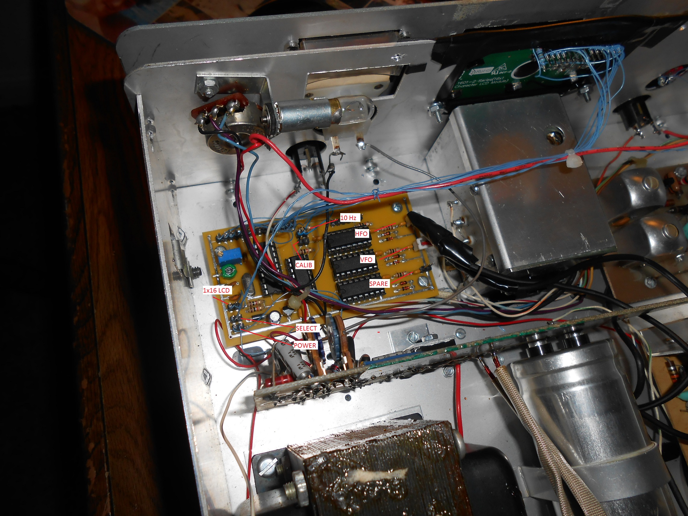
4. Adding the Interface
Board - Interface Board Schematic
The
logic in the digital display needs both the
heterodyne oscillator and the VFO (PTO) to compute the actual
frequency. To accomplish this,
a simple MPF-102 source follower is used for each signal.
Before
wiring up the interface boards, cut a small piece of either perf board
or P/C board and verify that it will fit on the rear corner of the
heterodyne oscillator board, close to the existing coaxial
connection.
Solder a ground lead from the interface board to the ground plane on
the mixer board.
Wire up
the boards and mount and connect them carefully, as shown here.
For the external display, you'll need to remote the Heterodyne
Oscillator, PTO/VFO signals and 12 volt power to the display. On
the Century's rear panel are three (3)
RCA jacks. Two of these supply 12 VDC, while the third is
used for the CW key. Three (3)
jacks
are needed to remote the digital display - one to provide 12 volt
power, one for the buffered PTO (VFO) output and yet another for the
heterodyne (HFO) oscillator output. By mounting a key jack
in the plugged hole in the rear of the chassis, and by severing the
power lead to one of the RCA jacks, you'll have a power lead and jacks
for both the buffered PTO/VFO and Heterodyne oscillator.
5.
Building, Calibrating and Connecting the Counter
Construct, test and calibrate the DFD-2 clone following these
instructions. The Heterodyne Oscillator and VFO
connections are
used - the BFO connection is NOT used and no chip needs to be installed
in the BFO position. The schematic can also be found here.
6.
Making a Suitable Enclosure - External Display
One thing you can still find at Radio Shack is a good plastic
enclosure. I used the smallest I could find (5 x 2.5 x
2 inches) that would hold
the
electronics which is stock number 270-1803 ($5.49). The plastic
in
these
boxes is easily
cut
with an Exacto
(or similar) knife. Some suggestions:
- connect the board to the LCD (using 30 gauge wire) and then test the complete
assembly,
- cut a hole for the LCD in the lid and mount the LCD,
- mount the board in the rear of the box leaving space for the
interface and power cables,
- for the Century 21 installation, mount a small SPST switch on the
front panel as this will be used for band selection purposes,
- wire this switch to the SELECT terminals,
- drill small holes for the interface cables and connect them to
the PCB. Use
just enough RG-174 to connect your display to the radio.
- test and calibrate your display and screw the box closed.
7.
Initial
Tests
Connect
the display to your Century 21 and turn the power on - both the Century
21 and your display should light up and some frequency should be
displayed. If the wrong band
is displayed, just flip the band select switch.
8.
Counter Calibration
The counter needs to be calibrated to
insure accurate frequency reporting.
There
are at least two ways to calibrate it. Whichever you use,
let
both
the Century 21 and the digital display warm up for at least 15 minutes:
The easiest way is to tune in a station whose
frequency is known and then gradually 'tweak' C13 until the display
mirrors the known frequency. When doing this, go slowly as
the software computes the HFO every 4 seconds while the VFO
frequency is computed and displayed every 1/4 second.
Alternatively, if you have an accurate
frequency counter, measure the HFO frequency and jot it down.
Then connect the board's HFO
input cable to the
radio's HFO output and disconnect the VFO plug.
Place a jumper on the TEST connector and the
display will now
be converted into a very accurate, single input frequency counter in
its own right. Adjust C13 until the frequency on the display
exactly matches what you had previously recorded during the HFO
measurement,
power the board down, remove the jumper from
the TEST pins, reconnect the VFO lead, power and you're good to go.
9.
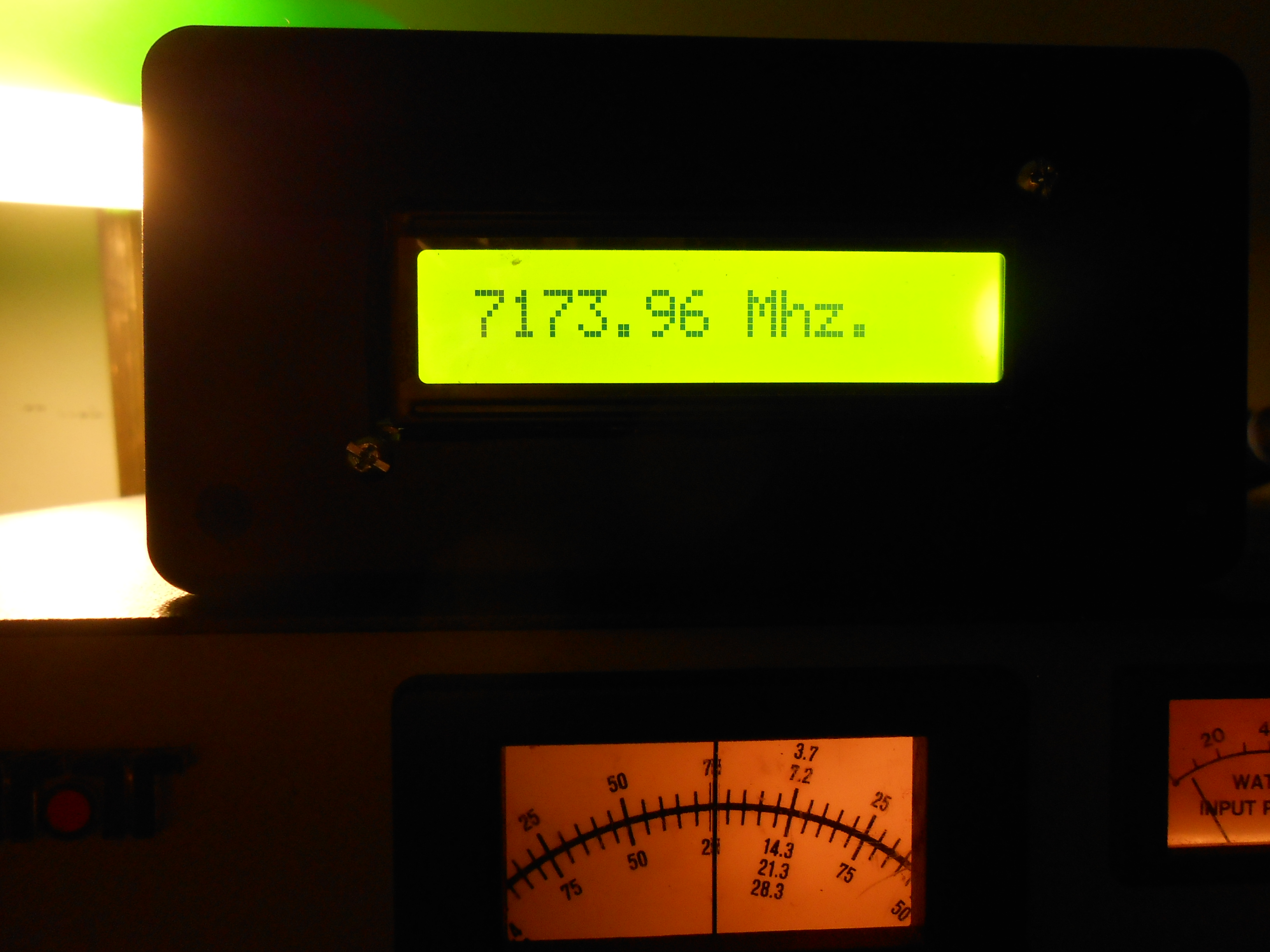
Using the Digital Display
Using the digital display is very easy - just set
the bandswitch and note the frequency. Changing the offset control while
in the receive mode
will make corresponding changes
to the digital
display - neat-o!
10.
'Birdies' - Remote Digital
Display- Most are either
obliterated or severly attenuated by band noise....
- 80 meters -
3600, 3705, 3750, 3857, 4000.
- 40 meters
- 7030, 7142, 7211, 7291.
- 20 meters
- 14000, 14062, 14143.
- 15 meters
- 21051, 21118, 21142, 21198
11.
'Birdies' - Internal Digital
Display
- 80 meters - 3500, 3600, 3656, 3681.
- 40 meters - 7030, 7050, 7065, 7082, 7101, 7142.
- 20 meters - 14000, 14062, 14143,
- 15 meters - 21051, 21089, 21118, 21198
12. - Internal Digital Display
- remove all knobs and nuts from the front panel, temporarily
disconnect the wires to the meter and front panel push buttons; remove the front panel.
- remove the 4 spacers from the controls and remove the nuts
holding the controls, and place the driver and offset pots back out of
the way.
- remove the screws holding the front panel and don't lose the 4
fiber spacers securing the PTO to the front panel,
- remove
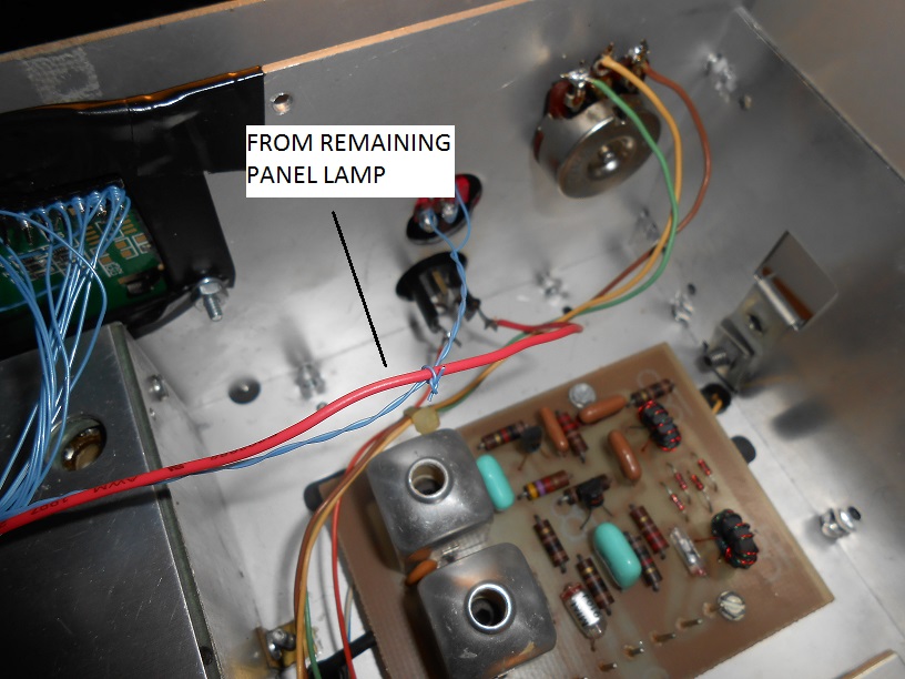
the scews holding the (2) panel lamps that backlight the display window
and sever the red power wire that runs to the lamp above the meter.
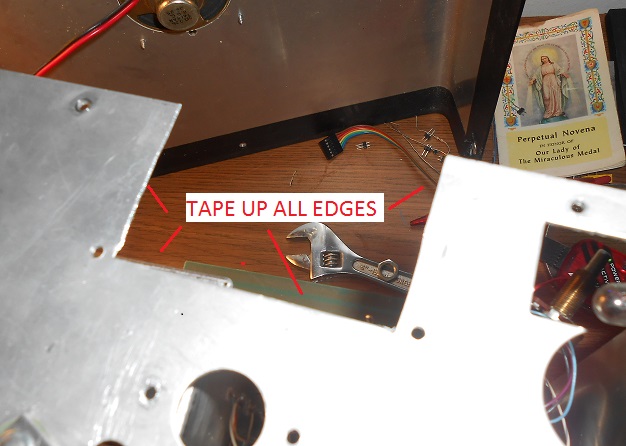
- center the LCD that you plan to use and carefully cut out an
opening for it so that the complete LCD will fit flush against the
FRONT of the sub panel, like so.
Center it above the opening for the PTO. A tin
snip cuts the metal very nicely. If you like, you can cut straight down
from the top without causing any problems. The software has been
adjusted to properly position the frequency information within this 'window'.
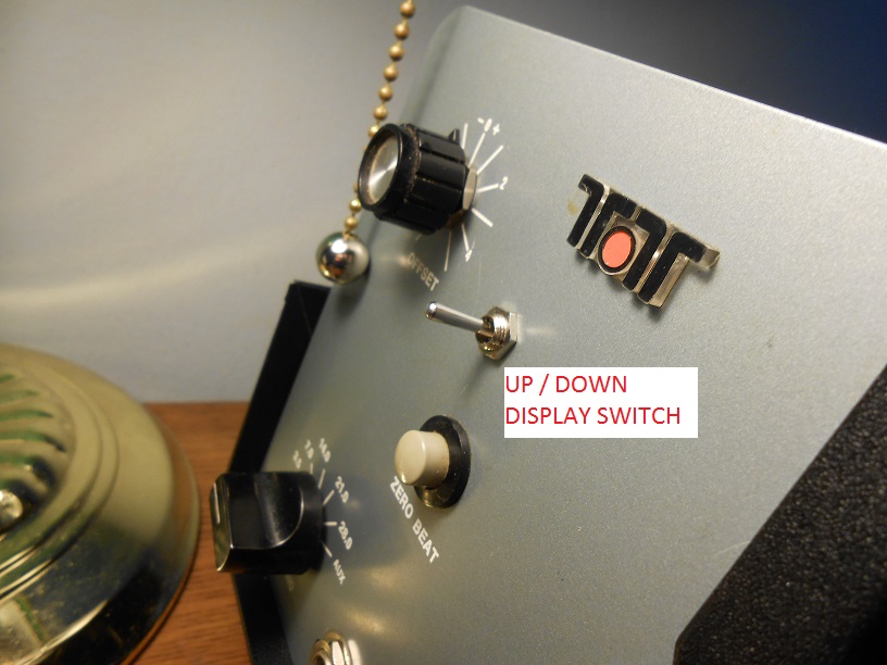
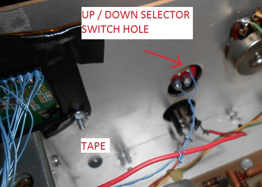
- carefully dril a hole in the front panel to mount the frequency UP / DOWN switch.
- make a corresponding hole in the sub-panel so that the switch connections will not short out.
- drill two mounting holes for the LCD (one at each bottom
corner). You should not need to remove any of the bottom. Measure twice - cut once.
- affix the LCD to the FRONT of the sub-panel with screw spacers that ensure
that there are no shorts to ground. Tape
up the front of the LCD so that none of the LCD backnight will shine
through when powered up. The same is true for the one remaining
lamp above the meter.
- wire the LCD to the controller and test it to ensure that it
works - use one foot of 30 gauge wire (Radio Shack) for each connection.
- temporarily power up the controller and verify that the LCD works.
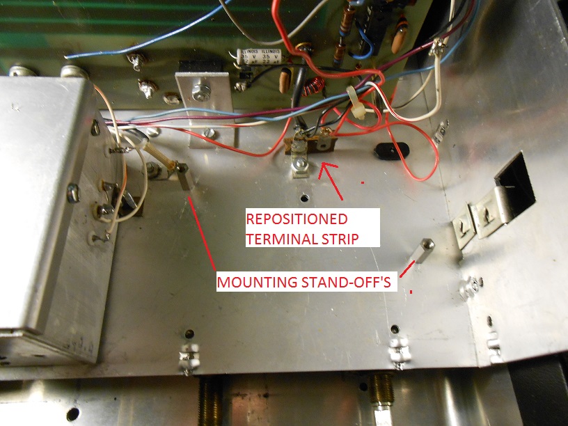
- reposition the two conductor terminal strip on
the chassis behind the meter to provide a suitable mounting location
for the controller board. Temporarily relocate the board
underneath and use care when drilling through the chassis. The
controller power will be taken from this terminal strip.
- drill mounting holes for the controller - two should suffice. Mount it on standoffs made from 4-40 screws and nuts. Vacuum away any metal filings.
- run a new (red) power lead from the remaining lamp over to the other side of the SPOT button.
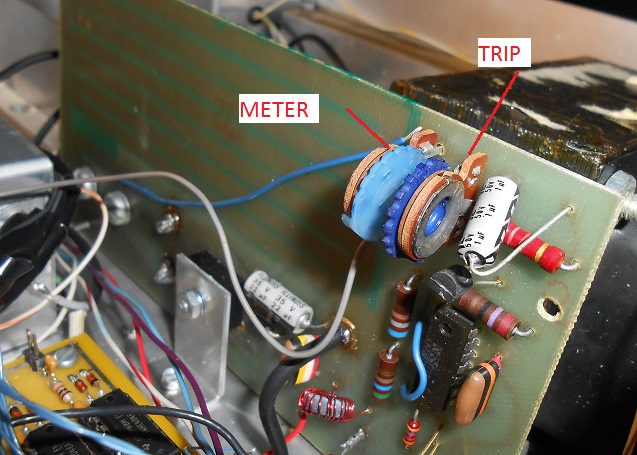
- connect the two terminals on the UP / DOWN switch to the controller board at the SELECT terminals (this is not currently on the schematic).
- ensure that the settings on the meter and the current trip
potentiometers have not been accidentally changed when you worked in
this area. You can find set up instructions in the service
manual.
I took a shortcut here because I know that the Centuy 21 will put out
40 watts when properly adjusted with a 100 watt resistor - as explained
in the manual. So, I connected the radio through an accurate
wattmeter and set the trip at 30 watts, just to be conservative.
- reassemble, calibrate and enjoy. You'll never be off
frequency again.
- save all the removed parts in the unlikely event that you want to
restore the radio to its original condition. Some black paper
would need to be taped to the display window on the sub-panel to
'replace the metal that was cut away.
Copyright 2016 -
K3JLS