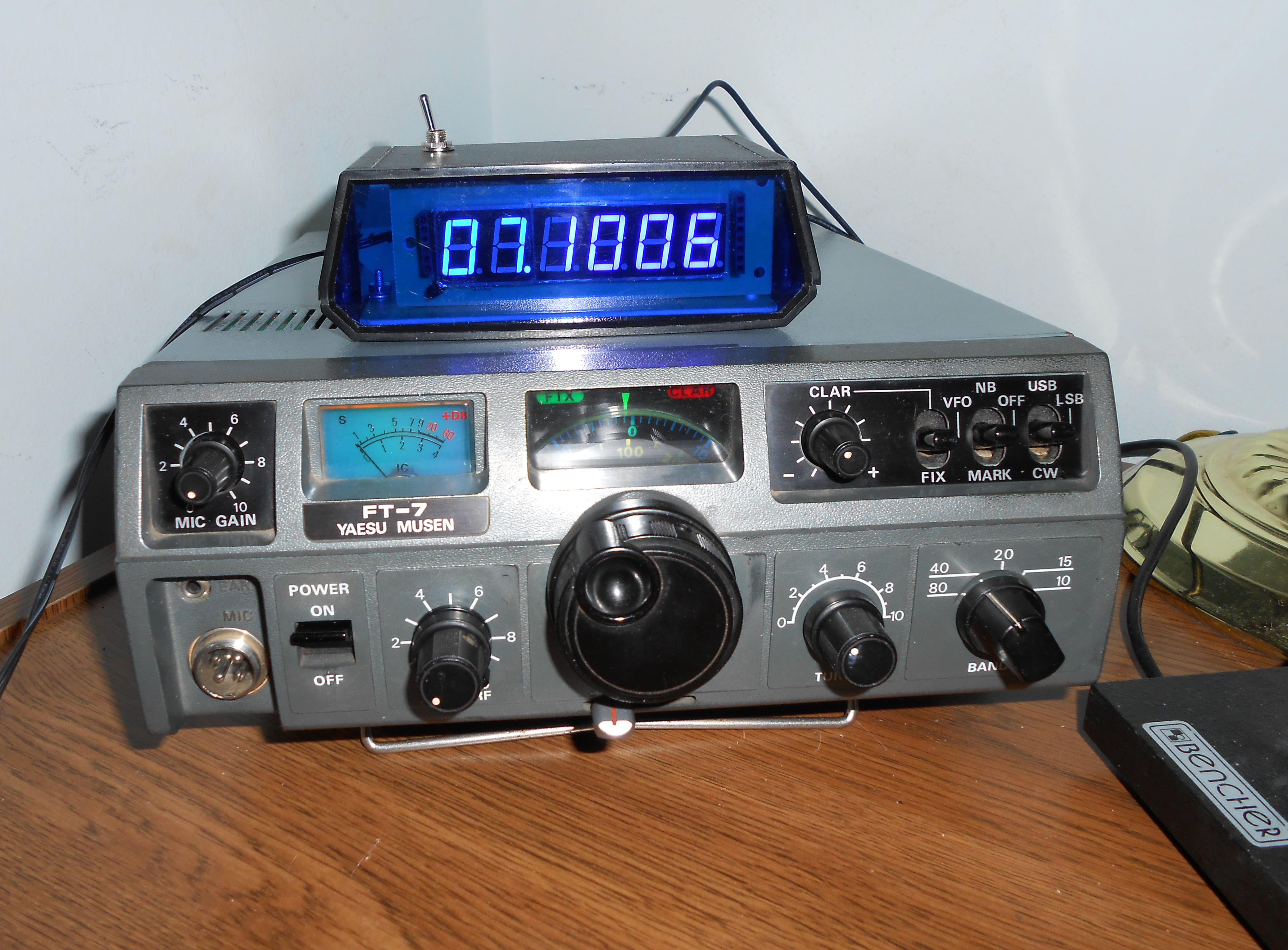
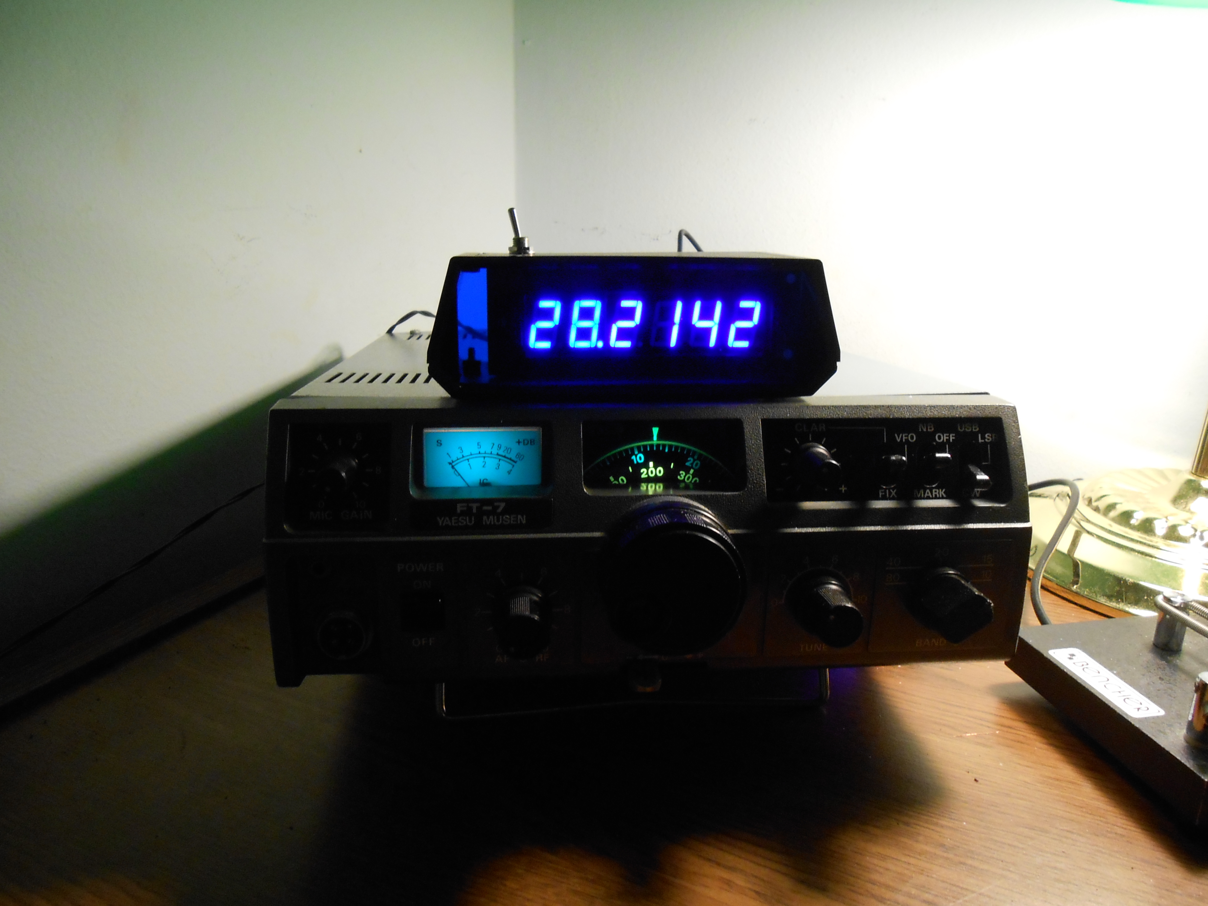
Yaesu FT-7 /
FT-7B Digital Frequency Display and Internal Keyer
Comments???
Service
Manuals:
The
Yaesu FT-7 and FT-7B were introduced in the late 70's / early 80's and
still enjoy a lively following because they are rugged and
dependable. Their receivers are free from the synthesizer by-products
associated with some of the more modern radios and they are
easy
to maintain Almost of the circuit boards are modular - easily
removed for service. The radio also takes up little shack
'shelf space'.
This website offers two
additional improvements to the many that have been published,
those available in the Yahoo FT-7 Users Group, and
those found by searching the internet. Specifically,
this website describes how to add an outboard digital frequency
display and an internal iambic keyer. Undoubtedly, other methods
of implementing these two features are also possible and the readers
are encouraged to improve upon what's described herein.
Both
the Yaesu FT-7 and the FT-7B use the same frequency
mixing scheme. Specifically, the 5.5 - 5.0 Mhz VFO signal
is premixed (subtracted from) the heterodyne
oscillator crystal
frequency (except on 80
meters where no heterodyne oscillator is used).
The mixer stage then subtracts the carrier oscillator
frequency (either 8998.5 khz or 9001.5 khz), producing the
desired USB / LSB / CW output.
- For 40 through 10 meters, the 8998.5 khz carrier
oscillator is used for LSB, while the 9001.5 khz carrier oscillator is
used for USB.
- For CW operation on all bands, the
8998.5 khz carrier oscillator is used.
- For 75 / 80 meter operation, the VFO frequency is mixed
directly with the carrier oscillators, reversed by the
bandswitch.
Yaesu
designed the YC-7B display to plug in at the
rear of the FT-7B. No such provision was made for the older FT-7.
The display interface between the FT-7B
and the YC-7B consists of 13 Volt power, ground and PREMIX input
connectors, as well
as CW, LSB, USB and 75 / 80 meters leads to preset the
down counter properly.
This website describes several external digital frequency display
possibilities and how the FT-7's buffered PREMIX signal can
drive these
counters with the
required signals developed at the FT-7's 5 pin external VFO
connector, or at the FT-7B's 7 pin counter connector (more on this
later).
a)
eBay Chinese Constructed 6
Digit Display -
PLJ-6LED-A - Unmodified
Consider this assembled eBay
6 Digit counter shipped from China for $12.
To use it, the
FT-7 will require an additional buffer circuit. The FT-7B will
work as is. Connect it after you have verified that the FT-7 / FT7B's
carrier oscillators are precisely on frequency.
- For CW operation on all bands (except for 80 meters) and
for 40 meter LSB, program the counter to subtract the 8998.5 khz.
- For 20, 15 and 10 meter USB operation, program the
counter to subtract 9001.5 khz.
- The
'stock', unmodified version of this
counter will not work on either 75 or 80 meters.
- Here's a Youtube
video showing how to program the unmodified PLJ
-6LED-A 6
DIGIT Display / Counter.
b)
eBay Chinese Constructed 6
Digit Display -
PLJ-6LED-A - MODIFIED
Using a rewritten version
of the PIC16F628A software designed by Wolfgang Buescher, I
modified the PLJ-6LED-A device to both work on 75 and 80 meters as well
as the other bands supported by the FT-7 / FT-7B. It took
some time to make this work as the interface between the PIC processor
and the TM1637 chip driving the LED's had to be developed.
Once this was done, an I2C interface had to be devised and
then several timing changes made as the Chinese counter uses a 13 Mhz
time base whereas Wolf's circuit uses a 20 Mhz crystal.
A simple sideband select switch
on the top of the enclosure is required, and that's it.
The display is
very accurate and responsive. Contact me if you are interested
in purchasing a modified unit.
Note: A
suitable enclosure needs to be built.
A Radio Shack
small box (cut out with an exacto knife) will do nicely.
c) DL4YHF Display - Three
Variants - Check
Out the FT-7 Buffer
/ Display Driver Requirements
Wolfgang Buescher - DL4YHF
- designed an interesting and accurate 6
digit display using the PIC 16F628A
that can either be homebrewed, or purchased on eBay as a kit
from
Ralph Van Dyke (the newer version - shown below). I've built
2 of Ralph's kits, one for my Drake
B Line and
another for this project. They both come with a nice plastic
enclosure and blue LED's - really sweet! Unlike the unmodified
Chinese 6
Digit Display, this device can be readily
manipulated to (optionally)
detect and then subtract
the carrier oscillator frequency 'on the fly' with a few key presses, or by flicking a simple switch.
The digital display
counter interface is already built into the FT-7B (Q1 - an emitter follower),
probably somewhere on the backplane board. The base of this
transistor connects - through a small coupling capacitor and very short
lead - right to TP-1902 (pin 14), the output of the PREMIX oscillator.
To
replicate this circuit in the FT-7, a comparable driver needs to be
fabricated. However, it would be extremely difficult to mount
this circuit in close proximity to TP-1902. I used
a short piece of miniature coax from pin 6 of
the mixer board (underside the chassis) to drive the modified buffer
circuit, virtually identical to the emitter follower circuit used in
the
FT-7B (see
schematic).
- Direct Conversion -
The software can be pre- programmed to include the LSB and
USB offsets to be subtracted, specifically 8998.5 khz and 9001.5 khz.
When changing bands, the user must remember that 8998.5
khz will be used for all CW work and for 40, 20, 15 and 10
meter LSB and for 75 meter USB. Conversely, 9001.5 khz will be used for
75 meter LSB
and for 40, 20, 15 and 10 meter USB.
- Using the PGM
button, toggle down to TABLE
- Select either 8.9985
or 9.0015
- Enter a long keypress
- Select SUB
tract and hold until it blinks
- Release the PGM
button.
- Switched Sideband Conversion
- The software
can be modified so that a single switch on the top of the display
enclosure will switch the mode of operation (i.e. CW/LSB or USB).
In so doing,
the counter will work only with the FT-7 / FT-7B.
- Use switch Position A for all CW,
80 meter USB, 40 thru 10 meter LSB
- Use switch Position B for 80 meter LSB, and for 40 thru
10 meter USB.
- Push
Button Conversion -
A relay interface to the FT-7 / FT-7B frees the
user from remembering these 'rules'. The operated relay samples
the carrier oscillator frequency and - after which a few button
presses - the display will subtract the carrier oscillator from the
PREMIX
frequency. A top mounted switch will operate the relay and
a push button will be required to program the
counter.
- Operate the SAMPLE
switch on the display and the actual carrier oscillator
frequency will be displayed,
- Using the PGM
button, toggle down to SUB
tract
- Hold the display push button down until SUB blinks,
- Release the PGM
button (and
the display will show all zeroes),
- Release the SAMPLE
switch and the actual frequency will be displayed.
d)
Installation Suggestions
For the internal keyer and / or the Push
Button Conversion,
the rear of the FT-7 / FT-7B is removed to install a
miniature 3
conductor keyer jack and keyer command button. The Push Button
display conversion also requires a minor FT-7 (External VFO jack) or
FT-7B (display jack) wiring change.
For the FT-7,
here are the connections on the 5 pin FT-7 External VFO jack where the
external display will connect:
- 13 VDC - pin 5
- Ground - pin 2
- VFO (coax) - pin 4
- +8 VDC - pin 3
- EXT 8V - VFO - pin 1
This
jumper between pins 1 and 3 is cut if an external VFO is used.
Remove the jumper and the two leads, connect these two
leads together, insulate the connection and stuff the wires back into
the radio. The
internal VFO will not work
if these two leads are not connected together.
Leave the other leads intact. Run a wire from one of
the 2 spare terminals back to the miniature relay connection on the
source follower counter interface buffer board.
For the FT-7B,
the digital display connections can be made directly to
the existing external display socket. No wiring
changes will be
required and no interface
board will be needed - UNLESS you are
installing the PUSH BUTTON
conversion.
The FT-7B has a buffered circuit already connected to
the PREMIX
output. Here are the connections on the 7 pin
jack to which the external display will connect:
- 13 VDC - pin 7
- Ground - pin 6
- Premix Output - pin 1
- pin 3 - CW - not sure, print is blurry
- pin 5 - LSB - not sure, print is blurry
- pin 2 - USB - not sure, print is blurry
- pin 4 - 3.5 - not sure,
print is blurry
For the PUSH BUTTON
conversion, use either pin 2, 3, 4 or 5 for the push button relay
control lead.
For the
internal keyer, mount both a SPST (normally open) push button switch
and a 3 conductor miniature jack on the rear panel,
running the wires up through the radio as shown.
Note:
The push button activates the keyer's command mode
and is installed at the rear to avoid drilling holes in the
front. However, additional transistor switching circuitry
could be installed to 'repurpose' of one or more of the front
panel
controls (like the MARKer or Noise Blanker).
I decided not to do this as I (very infrequently)
use the keyer command button just to change the keyer speed.
Remove the cover over the PA
filter board. Use cable ties to dress the
wiring neatly. In replacing the rear panel,
ensure that nothing is pinched.
For the FT-7
6 DIGIT
or DIRECT
conversions, build the emitter follower counter interface
board that will buffer the PREMIX
signal sent to the counter. Reuse the output coaxial
cable running to the rear
mounted external VFO connection, reterminating it as
shown here. Using RG-174 (or similar)
coax, connect the input to the buffer interface to the PREMIX output - TP-1902,
topside.
Mount the board with double sided tape under the VFO.
For the FT-7B 6
DIGIT or DIRECT
conversions, just connect the display to
the rear display connector, following the output pin conventions.
For the FT-7B PUSH
BUTTON
Conversion, you can either modify the
existing internal wiring to allow a miniature relay to switch the
output between the PREMIX
(TP-1902) and the carrier oscillator (pin 7 or 8 on the IF board),
or implement the interface circuit described
herein - your choice.
d)
Display Calibration
For the 6
DIGIT, DIRECT
and SWITCHED
SIDEBAND conversions,
it's important that the LSB and USB
carrier oscillators are set precisely
on frequency as the counter's firmware will subtract this
frequency from the PREMIX.
You may use either an accurate digital frequency
counter or a radio with a good digital display to accomplish this.
Note: If you use a
frequency counter, measure the carrier oscillator outputs at either pin
7 or 8 on the IF Board.
Setting the carrier oscillators for the PUSH BUTTON
conversion precisely on frequency is not terribly important as the counter will measure the actual carrier
frequency which will be subtracted from the PREMIX frequency.
For the DL4YHF conversion, the time base
of
the PIC 16F628A must
also be set. You may calibrate the time base by first
carefully tuning the FT-7 / FT-7B to a
SSB station of known frequency - say, one that is being received on
another station receiver - and then adjusting the time base until the
FT-7's display matches that of the other, verified on another, known
accurate station receiver. Alternatively,
you can zero beat the PIC's 20 Mhz time base with a good receiver tuned
to 20 Mhz, perhaps zero beating it against WWV, if you can receive it.
Note: The
Chinese 6 Digit LED counter has already been set at the factorY and
does not require any readjustment.
c) Modified Software for the
DL4YHF Counter
The software for
the modified DL4YHF
counter is finished and will be available from Ralph Van Dyke shortly.
d)
Internal Iambic Keyer
I decided
to purchase the Jackson Harbor
Press PK4-SSR unit that I've used in other projects. The Jackson Harbor
Press keyer board is mounted on the P/C
board formerly used for the FIXED frequency. This
board was
stripped of all its components, the Jackson Harbor Press keyer mounted
with 1 stand-off screw, and connected with 30 gauge wiring to the
proper pins on the stripped FIXED board front / rear.
The under chassis wiring
connects to the proper points in the radio. This way, the
keyer
may easily be removed from the radio, if necessary.
Notes:
Before making any under chassis connections to the FIXED
board position, remove all the wires
to the bandswitch.
You may remove one of the chassis side covers as the
space in there is tight, or even remove the switch wafer itself (be sure you remove the right one).
Power (8 VDC) for the keyer board may be
found on pin 1 of the topside chassis mounted resistor board, and this
power source can also be used for the MPF-102 source follower interface
board,
if used These are the pins that I used - other connections
are - of course - possible.
- Left Paddle - Pin 13
- Right Paddle - Pin 2 -
sever the trace on the underside of the board to the next connector.
- Command - Pin 12
- Power - Pin 5
- Ground - Pins 6,7, or 8
- Key - Pin 9
- Audio Out - Pin 3 - sever
the trace on the underside of the board to the next connector.
- Connect
the Audio Out to pin 15 of the AF board through a .01 mf capacitor, and
program the keyer to turn the sidetone and sidetone float off.
Important Note:
When using the internal keyer, insert a dummy (open) miniature
plug in the existing key jack to 'satisfy' the FT-7 - FT-7/B.