Important Note: Unless
you are absolutely
certain that you know what you are doing, do
not perform this conversion.
I cannot be
- nor will be - responsible for
any damages
to your radio incurred as a result
of your reading this website.
A
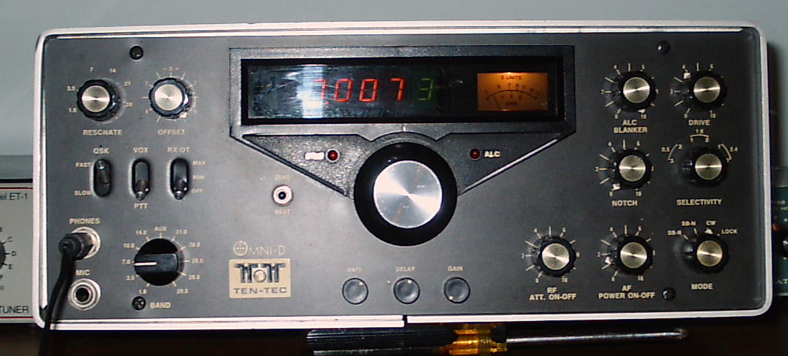
Dual Digital VFO for the Ten-Tec Omni A, B, C, D, Corsair, Century 21, Argosy, Triton, Delta, Drake TR7 & Similar
Digital Display, 5.0 to 5.5 Mhz VFO / PTO Equipped Radios
- Other
Omni Information / Modifications
- Service
Manuals and Miscellaneous Information
1. Introduction
Although
this site currently describes how this DDS VFO can improve the
Ten-Tec Omni D series of PTO controlled radios, it may be readily
installed in other Ten-Tec radios including the Corsair I and
Corsair II, the Triton, the Delta, the Argosy II and the Digital
Century 21 as these radios are all equipped with a factory stock
digital display.
However, if the user is willing to install a home brew digital
display, other Ten-Tec radios like the analog Century 21, the
Century 22 or the early Argonauts could likewise enjoy the benefits of
this conversion, provided there's space within the radio to
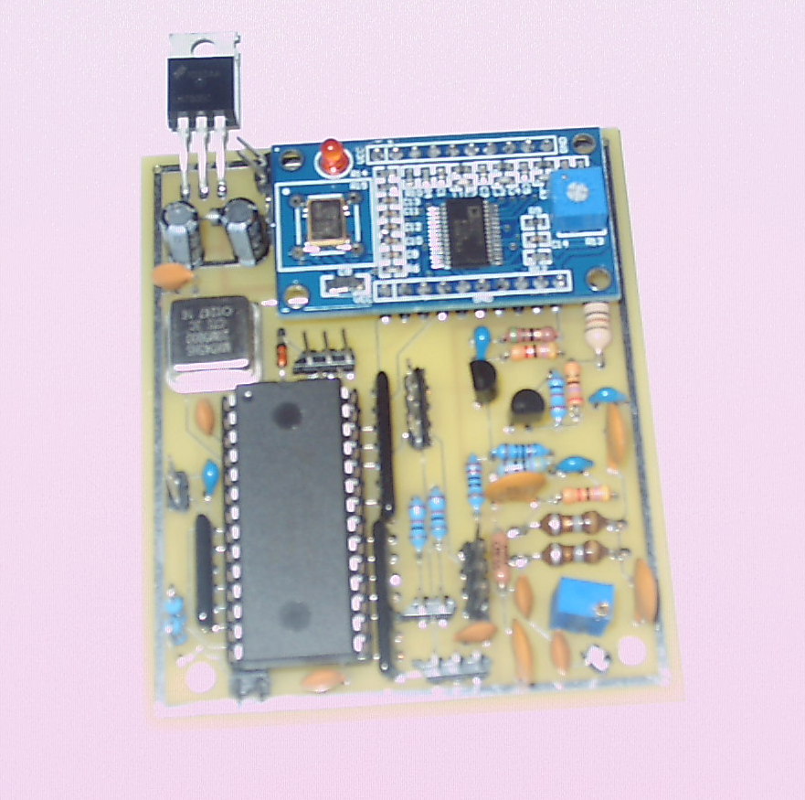
accommodate the DDS VFO circuit board which measures 2 and 3/4 by 3 and
1/4 inch. Removing the stock PTO should provide an adequate mounting space.
2. The 'Contributors'
- Giving Credit Where
Credit Is Due
Having built an AD9850 DDS signal generator using
a modified
version of George
Heron's (N2NAP's) code, I decided to develop a quality DDS
VFO using additional information published on the internet.
This website shares my results (and even the software) for anyone who might like to partake.
Porting George Heron's DDS software
to
a Freescale MC908JL16 chip was easy. I
bought a Chinese AD9850 DDS chip boards on eBay for $6 (including
shipping). Since it used a 125 Mhz crystal, I changed
the
multiplication constants in
George's software, and
it worked right off.
The output of the DDS chip needed
amplification. An internet search
produced a 2 transistor amplifier
designed by K8IQY.
Once breadboarded and operational, I had a nice 4
volt
peak-to-peak output. I sold off my old Heathkit
SG-8
and began to experience the wonders of DDS.
I then reworked the N2APB
code into a dual 5 - 5.5 Mhz VFO with SPLIT
operation, RIT and LOCK. Also included was an
interrupt driven tuning acceleration algorithm that significantly
facilitates traversing from one band edge to the other, as was the ability
to store the last used frequency so that it was available on power up.
This
VFO tunes much like an analog VFO with flexibility depending upon
the speed and duration of the optical encoder.
Note: a 128 step optical encoder will enable a frequency excuirstion of about 5 khz for each complete rotation. A 256 step encoder will double this to 10 khz. In my opinion, either is totally satisfactory and there are most often economical choices on eBay
Note: This VFO could
also be housed in a metal enclosure
and
serve as a versatile dual VFO for those reluctant to
modify their Omni, TR7, etc and / or don't want to take the time (and expense) to
rebuild the mechanical PTO. Here's just one example.
3. Parts - Itemized
Component List
You'll need about $60 - much less if you have
a well stocked junkbox. The most expensive part is the
optical
encoder. I found a couple of nice ones on
eBay
for $20 each. Truly clever folks may be able to
construct their own encoder using photo-diodes and a
home built optical interrupter with 'bearing type' parts from discarded
potentiometers. Surf
the web for suggestions.
Two P/C boards have been designed so that the Chinese AD9850
board will
plug right into it. Here are pictures of the prototype Version 1 board (no longer available), the schematic,
the P/C board 1 artwork , the wire connection points and
the first completed assembly.
4. Conversion Suggestions - Ten-Tec Omni Radio
If
you plan to undertake this conversion, the first thing is determining
how to mount your optical encoder. To do this, you'll
have to
disassemble the radio to the point of removing the front panel.
You might want to get a small container for all the knobs,
parts,
screws, etc.
a) Disassembling the
Omni (as an example).
- Remove the top and bottom
covers. On the bottom
cover,
you'll probably note that the speaker connection coax is rather short
and has not been provided with a quick disconnect
plug. To save a lot of frustration and possible
subsequent damage,
just unsolder the wires at the speakers.
- Remove the 2 screws holding
the notch filter
and set it out of the way. There's no need to cut any wires.
- Remove the support bar behind the digital
frequency display and the large screw behing the display itself.
- Remove
all the knobs. The 3 VOX controls pull off.
The
bandswitch requires a small slotted screwdriver. The remaining
knobs require a very small (.05)
allen
wrench.
Note: Be sure to
save the 2 felt pads from the main tuning knob as they will come in
handy later.
- Unscrew the nuts securing the PHONES
and MIKE jacks and retain the flat and lock washers.
- Remove the 4 phillips screws at the
panel's corners.
- Gently
slide the panel (and the trim ring) forward, removing the nut holding
the SPOT button, unplugging the small connector that provides power
to the OT and the ALC lamps. Once done, set the panel aside and turn the radio over onto its
top
- Remove
the 3 front panel nuts securing the VOX board and the retaining nut in
the rear. Move the VOX board away from its mounting position
as
you'll need the additional space to rotate the PTO before its removal.
- Flip the radio over and remove the 4
panel screws holding the digital display and carefully set it back - no wires need be cut.
b) Removing the PTO
- Remove
the 2 front panel screws securing the PTO and twist the PTO
so that you can either clip or unsolder the 3 wires and coax
connections to it. You might want to leave a slight bit of
color
coded wire on the PTO lugs if you ever plan to reinstall it.
Tape the wires and set
the PTO aside.
c) Installing the Optical
Encoder
Before installing the encoder, make sure your board is working
properly. Following the schematic, connect up the encoder, a
frequency counter to the output and then 12 VDC and ground.
You should see a 5.000 Mhz signal (or something very close)
which should change as the encoder is rotated. If you don't
have
a counter, your station receiver will suffice. You can even
connect it directly to your Omni at the rear jack provided for a remote
VFO.
Important Note:
The DDS VFO output level should be set as close to the output of the
Omni's PTO as possible as the Omni's circuitry was designed around this
value. Setting the DDS VFO's output higher than this will
generate some 'birdies' here and there and needlessly increase the receiver's
background noise level. The Ten-Tec's PTO's output is approximately .5
Volt
peak to peak. A resistor trimmer (R5) has been provided on
the
Version 2 circuit board for this purpose. If you have a 'scope,
you
may use it to set the DDS VFO's board right on the money. If
not,
just turn R5 slowly until the radio begins to receive properly on all
bands, but no higher.
Also Note:
If you monitor the signal on your receiver, you'll probably observe a
rough, warbling note. This is normal as the RIT
connections
have
yet to be made and the processor's A/D converter (used for the RIT
function) will be 'hunting' a bit.
Connect 4 (2.5 foot strands) strands of 30 gauge wire to the encoder.
Tag the power and ground connections (I used knots in the
wire).
The phase leads can be swapped later (if it tunes
backwards).
In this case, the size (length) of your encoder shaft matters.
By far, the easiest way is to place a small
metal plate (drilled
out for the outside
diameter of your encoder
and mounted in the existing
PTO mounting holes) on the outside
of the radio's sub-panel. Temporarily install your encoder
(finger tight) and then the front panel. If you can
satisfactorily attach the tuning knob of your choice, and if it spins
properly - that's great.
But if you need a bit more
shaft length, either check around for another tuning knob
whose set screw is closer to the back of the knob and / or attempt to
drill out the old Ten-Tec tuning knob using a 1/4 inch bit and a drill
press. I tried
to my old knob
out with just a hand drill and muffed the job because the knob
had
a slight wobble when tuning.
To use the tuning knob of my choice
whose set screw was too far
back to securely grasp the optical encoder mounted on the sub-panel (as
shown),
I mounted the encoder on the front panel by securing it to the
same piece of drilled P/C board material which itself was mounted on
the rear of the front panel
using the two existing screw holes. Here's
a picture of the panel.
That's a steel washer under the nut.
It fits perfectly, and it
tunes like a dream.
Since the optical encoder didn't fit into the PTO opening, I had
to enlarge
the sub-panel opening using a Greenlee chassis punch.
I
mounted the encoder with the wiring pins downward and didn't obliterate
the former PTO mounting holes. Once
you are satisfied that the front panel can be properly installed, add
about 2.5 feet of wire to the old SPOT switch, mount it
on the front panel and temporarily set the whole thing aside.
d) RIT Functionality
The goal here is to give the controller access to the Omni's
offset control (RX-OT - 22K for my radio) and (optional) access to the
existing
offset switch.
First, remove the 4 screws holding the preselector
and turn the whole assembly backwards. You'll note
another
example of TEN-TEC's 'frugal' 'point-to-point' wiring
technique.
In my case, I was able to flip it back just enough to remove
the
Offset control from which I clipped all 3 wires.
Next, solder 3 wires (about 2.5 feet long) to the control, tagging the
center (wiper) lead, and set this control aside. If you want
to
use the existing Offset control switch and the OT led to indicate that
the offset mode (only on receive) has been activated, one more
step is required (see below).
If you don't want RIT on/off functionality, then there is no
need
to modify the switch assembly. If the RIT Disable lead is left open (high), the Offset
control
will be active
(except while transmitting). You'll have to set
it
properly when in the SSB mode (so that you're not off frequency).
Skip ahead
to this
step to reinstall the Offset potentiometer, the preselector,
the digital display and the notch filter.
Remove
the 4 nuts holding the switch assembly and push it back.
The mounting screws are inside the radio and they
are
equipped with vinyl spacers. The goal is to access to the
portion of the OT (offset) DPDT switch that controls the tuning voltage
being set to the PTO while the offset function is active.
Looking down from the front of the
radio, disconnect the two wires connected to the rightmost side of the
offset
switch. While there,
disconnect the
two wires from the SPOT switch. They can be tagged and
securely wrapped. Alternatively,
they can be removed if
you don't plan to revert to the PTO.
Two resistors (R2 and R4) on the switch board itself that need
to be removed if you want to use the OT switch to activate /
deactivate the controller's RIT function. Here's
a picture of one.
They have to be removed for the switch to activate /
deactivate the RIT function and light / extinguish the OT LED.
I wiggled the board until I
could see both 1/4 watt resistors through the hole and then clipped them both out
with needle nose pliers. The ideal way to remove these parts would be to
remove the 4 screws holding the board and then bring it up a bit.
However, Ten-Tec's stingy wiring practice struck again.
Needless to say, if you clip out these resistors it will
be difficult restoring the rig to its PTO condition without a lot
of
additional work.
Carefully
solder wires (each about 2.5 feet long) to the two upper, rightmost
portions of the offset switch. Once done,
use your voltmeter to
verify that the switch shorts when the offset is off, and that this
short is removed when the offset switch is in either of the 2 upper
positions. Run this wire as you've done with
the previous ones.
Using needle nosed pliers, carefully replace the vinyl spacers
that may have fallen off their screws and bolt the switch assembly up.
Reinstall the OT control on the front
panel and run the wires
beneath the chassis. Before
tightening nut on the OT control, connect a meter and set the control
to its exact electrical center (11K from the wiper either leg).
You want to ensure that this position will be maintained when
the
OFFSET knob is installed. It
should point directly up - for a zero offset.
Replace the preselector
assembly followed by the digital display and the notch filter.
e) Reinstalling the Front
Panel
Ensure that the leads for the optical
encoder, the SPOT switch,
RIT on / off (if used) and the Offset control are all run properly.
Ensure that the three flat 'black donuts' are mounted over the
toggle switches beneath the preselector and that no wiring is kinked /
snagged. Move the front panel close to the chassis and
connect
the 3 wire plug that operates the ALC and OT lamps and then place the
panel AND the trim ring in place, securing it with the
4 corner screws.
Remount the mike and headphones jacks, placing them in the
proper holes along with the large lock washers.
Place
a 1/4 flat washer up against the optical encoder shaft followed by the
2 felt washers removed earlier, and then mount the tuning knob.
If
your encoder has little to no torque resistance (as one of mine did),
the felt washers will keep the knob from unduly rotating
after it
has been turned and released.
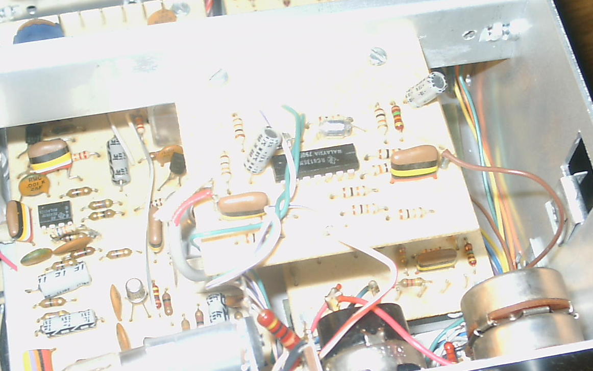
f) Mounting the Controller
I mounted my board in the right rear corner of the radio where the crystal calibrator mounts in the analog Omni A.
This is a convenient spot as it
has both a source of 12 VDC and existing coaxial cable access to the
VFO amplifier board to which the existing PTO is connected.
This
spot permitted last-minute refinements to
the M/P code (during the debugging phase) without removing the front panel, digital display, etc,
etc.
The ideal way to mount the controller would be to drill 4
holes
in both the corners of the P/C board and then into the chassis,
providing a physically secure grounding arrangement.
Being pressed for time, I mounted a piece of insulating
perf board under my P/C board, and secured this
with one
of the existing screws used to hold one of the connectors on the other
side of the board. One of the 2 P/C board mounting screws is
located in the corner of this board, while the voltage regulator
grounding tab is used for the other. I installed a longer
screw
in an existing hole (see picture). Grounding wires at the
other
corners of the board are connected to convenient locations.
Note: Since the whole board draws close to 140
ma,
the
LM7805 needs a heat sink, and the chassis alone is
perfect.
g) Connecting the
Controller
After
the controller is mounted securely, it can be wired up:
- connect the metal tab on the LM7805
voltage regulator to an existing nut that holds a terminal strip (on
the other side of the chassis).
- run short ground wires from each
corner of the board to nearby grounding points. For example,
there are 2 grounding points on the SSB Generator board that can be
used.
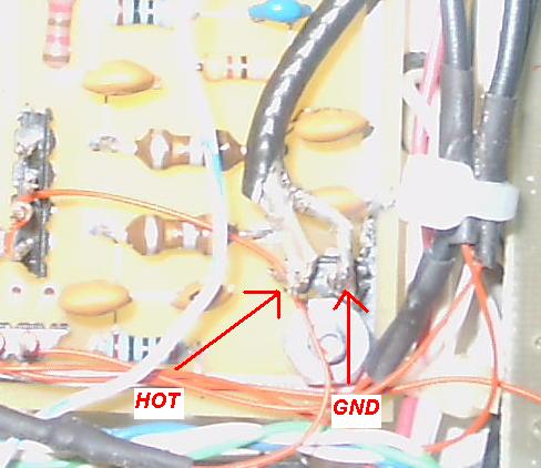
- next, connect up the 12VDC supply.
Because I mounted the board underside the chassis close to
the external VFO jacks, I tapped into this 12 VDC source.
When making this connection, I used a T37-2
toroid almost completely wrapped with 24 gauge wire in an
attempt to keep any RF energy from the Omni from interfering with the
DDS. This is
probably not needed, but I had a supply of toroids on hand, so - why
not??
- once these connections are made, turn
the radio on and verify that the red LED on the DDS board lights up.
Then, turn the radio off.
- connect a short length of RG-174 coax
from the AMP
OUT pins on the DDS controller to the connection where you
externally tested your controller.
- turn the radio on again and note the
digital display. It should show a frequency close to the low
end of the band. Then turn it off again. The next
step will be wiring up the optical encoder.
- there are four (4) connections for the
optical encoder - +5VDC, ground and the two phase connections.
You need to be
careful as
reversing the power and ground connections could ruin
your encoder.
- using your voltmeter, double-check both the +5VDC and
ground connections on the controller board. They are located on JP-4.
The connection at the TOP
is GROUND
and the one at the BOTTOM
is +5VDC, as shown here.
Make both connections.
- Next, connect the remaining 2 phase leads to the remaining
pins, power up the radio and turn the encoder. If the
frequency changes properly (i.e. clockwise is up), then this is done.
If not, just reverse the two phase leads. You've a
50 / 50 chance on being right the first time. Once done, you
should be able to tune the radio.
Take
note of how the tuning acceleration algorithm works. Unlike
the PTO scenario, one can get to either band edge in a hurry. Connecting the RIT
pot is next..........
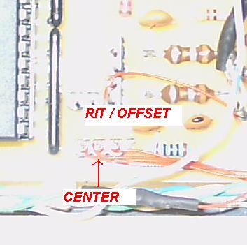
- Identify the wires running to the rewired 22K
Offset pot. Connect the tagged center wire to
the center pin on the RIT connector on the controller board, as
shown here.
Connect one remaining wire
to the lug at one end, and the other wire to the other spare lug. Turn the radio on and vary the OFFSET / RIT
control. If the
OFFSET control works in the proper direction, you're done. If it tunes backwards, then just
reverse the wires.
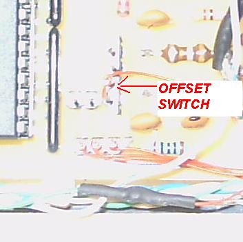
- If you've modified the Omni's OFFSET switch to enable /
disable the RIT function and light the OT lamp, you'll have to
make another connection. If not, skip to the next step.
Identify the two wires connected to the front panel offset
switch and ground one side somewhere on the controller board. Connect
the other side to pin 3 on JP6, as shown here.
Verify that the OFFSET function is disabled when the OT
switch is Off. Tune in a station and turn on the OT switch
(either up position). Vary the offset tuning and note the
signal change. Turn the switch off and note that the
frequency is changed back to its original. There should be
about 1.2 khz available on either side of 'top dead center'.
- Identify the pair of
wires connected to the push button switch
(formerly the SPOT control), and ground one side somewhere on the
control board. Connect the other lead to pin 3 on JP3, as
shown here. Verify that the SPOT switch - when briefly tapped
- will switch from one VFO to the other.
- The
last interconnection is for the lead that will cause the M/P to go into
the transmit mode, and care must be exercised in its
placement as it carries 12 VDC. If placed on
the wrong pin, this voltage will harm the M/P chip. This
connection is made on the Control Board, the one that's just
below the optional filter board. It's to be placed on the 'R'
pin
- the third pin from the right (from the side of the radio, looking at it from the front).
It's on the back of the board and can be reached without
removing
the filter board.
Note: Be sure that
you have the right pin by
measuring its voltage in receive (12 VDC) and transmit (0 VDC).
- Solder a wire to this pin and run it
through one of the chassis holes for connection to pin 1 of JP-3 the
DDS control board. Be sure you've
identified the proper pin. You might want to bend this pin a
bit
away from pin 2 to avoid the possibility of a cross. Verify
that the radio transmits properly.
5. Commands
When powered up, both the A and the B
VFO
will
be set to the lower band edge, that is, 7000, 3500, 1800, 28000 (etc).
VFO A will be enabled. The user may then tune with
VFO A in
the normal manner, and VFO A will be used for transmitting.
If
the RIT (OFFSET) switch is activated, the receive frequency will vary
based upon
its setting; the transmit frequency will not change. When
the
OFFSET is turned off, the original frequency will be restored.
To switch to VFO B, depress (tap) the function
button
(most often wired to replace the Omni SPOT button) briefly, and the
system will be using VFO B. The frequency previously stored
in
VFO A will not be changed.
Note: if you have wired up the optional LEDS, the LED for
either VFO A or VFO B will be illuminated.
To enter the SPLIT mode, just tap the function / SPOT button
twice (a short followed
by a longer tap - like a
' A' in CW) and the radio will enter the
SPLIT mode. The on-line
VFO
will control reception, while the off-line VFO will control
transmitting.
Note: if you have wired up
the optional LEDS, the SPLIT LED will be illuminated.
To exit the split mode, tap the function / SPOT button twice (another
short - long tap sequence) and the
radio will revert to the normal mode. The contents of the
on-line
VFO will be copied into the off-line VFO.
To
LOCK the system at any point, just hold the function / SPOT button down
for 2 seconds and the system will be LOCKED, and cannot be changed
until UNLOCKED. To unlock the system, just tap the function /
SPOT button - and that's it! While LOCKED, the RIT control will work.
Note: if you have wired up
the optional LEDS, the LOCK LED will be illuminated.
An
optional button
has been added dedicated
to the SPLIT
function. Tap
it one time and the SPLIT function is active. You can then
use
the main button to switch between the VFO's. Tapping the
SPLIT
button again will disable the split function and map the on-line VFO
into the standby unit.
To store the last used frequency before powering down the radio, just operate the LOCK function,
release
the button and push it again within
one second.
If you have equipped the LED's, they will all flash 3 times
to
indicate that the frequencies (VFO-A, VFO-B and the split function)
have all been stored in flash memory and will be available whenever the radio is next
powered up.
Note:
The instruction manual for this processor states that
the flash memory can be updated just 10,000 times, so you might want to
use this function frugally. If you want to disable it, simply
ground the FLASH INH lead (see the schematic).
7.
On-the-Air Results
a) Receiving
The P/C board is mounted
in the rear of the chassis, with no shielding and with rather long
leads for the Encoder, Offset and Push Button controls, and it works well for me.
Note:
One way to cut down on spurious mixing products is to follow the
instructions in the service manual to adjust both R23 and R2 on the oscillator / mixer board. Perform
the adjustments shown in Step 3 and in Step 7 (Mixer Balance).
With an antenna connected and the preselector peaked, there are a few detectable narrow banded (200
to 300 khz spurs). The
louder spurs are asterisked.
- 160
Meters - 1950
khz (this signal appears in the unmodified Omni and it can
be minimized by adjusting R23 - see service manual).
- 10
Meters (B) - 28978*
khz.
Note: This 10
meter spur (28987 khz is quite loud) is a known Omni issue. To tune this frequency, set
the bandswitch to the 29 Mhz position and tune downward. Check the
service manual for more information.
b) Transmitting
Several
SSB QSO's were made on 40 meters, and the reports were comparable to
what one would expect from a PTO equipped Omni - generally very good.
Both the SPLIT and QSK functions work
properly on CW.
8. Other Concerns /
Considerations
If the user decides to tune up the
antenna to make
a QSO
(say, answering a CQ), and if the antenna SWR is too high - the power
supply circuit breaker will trip. Since the DDS board is
powered
by the same supply, the desired frequency will be lost when the breaker
is reset. This
is one of the drawbacks of using DDS in lieu of
the analog PTO when the DDS is
powered by the current sensing power supply.
Three solutions are possible.
- The DDS board could be powered separately -
say by a wallwart supply -
and left on all the time. This way, should the Omni's power
supply trip out, the desired frequency information will be retained on
power up. Gauche? - yes, but workable.
- If
the AIRPAX (or equiv) circuit breaker used to safeguard the radio's
finals were to be installed in the Omni proper, then the DDS VFO could
be powered on the 'line side'. This way, the circuit
breaker's
tripping would not cut the power to the DDS module.
- Alternately, the operator may gradually increase output
power (using the drive control) when tuning up to an antenna.
9. Using an External DDS VFO Controller
- Front, Side, Rear Views
Those reluctant about digging into their radio to mount the
DDS VFO P/C board, encoder (etc), may opt to build the whole thing in a
separate enclosure as shown in the above pictures. As you'll
note, the prototype unit (just sold) has 4 unmarked LED's across the top (VFO-A,
VFO-B, SPLIT and LOCK), a red and a black push button, the tuning knob
for the optical encoder itself, and the RIT control with an activation
/ deactivation switch.
The rear panel shows
the power connector, the VFO output and a third phono jack into which
the transmit signal from the radio is to be plugged, as was done with
the internal modification (R lead) that was just described.
The black button
is the multi-function unit that lets the user switch VFO's, operate
split and lock the dial. The red button is just a one press
access to the split function.
Note: The unit shown here worked very well with both my Ten-Tec Omni and Drake TR7. Another ham is using it with his Corsair 1.
Loose
Chassis Grounding Screws
Intermittent connections are very often frustrating and difficult to
pinpoint / resolve. One such example involves the chassis
grounding method used by Ten-Tec on the RX Trimmer and bandpass boards
on the radio's underside. When the screws holding these
grounding
straps loosen, they can be very difficult to tighten as the PC boards
themselves limit access, and narrow needle nose pliers are often
required. Even worse, when the chassis threading becomes
stripped, there's no way that the screws
can be secured.
A simple solution is to insert a short screw in the chassis hole
beneath. Then, solder a short bare wire to the topside of the
board and secure it to the new screw, as shown here.
Intermittent
Heterodyne Oscillator Crystals - Check the Chassis Grounding Screw and
the Crystal Pins
I purchased my Omni used on eBay. The seller mentioned that
the
40 meter band was sometimes intermittent, and would usually work after
the radio had warmed up for a bit. He was right. I
spent a
couple of hours on this problem noting that the 80 meter band would
occasionally crap out. Two bad
crystals???
I put a scope on the output of the oscillator / mixer board and
watched. When the 40 meter band was starting to fail, the
output
of this board would start to gradually diminish to the point where the
received signal would weaken and then totally disappear.
Sometimes the display would remain on frequency, but most
times
it would just revert to 1.000 Mhz.
I found
that I could restore operation by tapping on the crystal band and / or
just flexing the board. However, one problem was positively
traced to a loose grounding screw which is partially hidden by the
oscillator / mixer board itself. There was enough of the
screw
'showing' so that I was able to tighten it with a small bladed
screwdriver, and this solved my problem at least for a while.
While you're at, try
tightening up all similar grounding screws on the bottom of the chassis.
Here's a picture.
Poor quality? - yes, but it should point you in the right
direction.
After a week or so the problem reappeared. So, I turned the
rig
off, let it cool and then removed the bottom cover. Upon
power
up, 40 meters worked for a while and then began to fail. I
found
that I could reproduce the problem by slightly tapping on the 11 Mhz
crystal.
So, I removed the crystal from its
socket, cleaned the pins and then reinserted it. No good.
There was either a poorly soldered connection on the bottom
of
the crystal socket, or the crystal was intermittent. Then I
noticed that the crystal worked perfectly well if it was only partly
inserted into its socket.
Next, using a
toothpich I carefully narrowed the openings on the crystal socket.
I also gently spread the pins of each crystal so that a bit
more
force was required to insert them. So far- so good.
No
matter how I tap on the heterodyne oscillator board or the crystals
themselves, I cannot repeat the failure.