Important Note: Unless
you are absolutely
certain that you know what you are doing, do
not perform this conversion.
I cannot be
- nor will be - responsible for
any damages
to your radio incurred as a result
of your reading this website.
A
Dual Digital VFO and Display for the Ten-Tec Triton 540
PRELIMINARY
- Other Triton Information / Modifications
- Service
Manuals and Miscellaneous Information
1. Introduction
Although
this site currently describes how this DDS VFO can improve the
Ten-Tec Triton 540, it may be readily
installed in other Ten-Tec radios including the Corsair I and
Corsair II, the 'Omni's', the Delta, the Argosy II and the Digital
Century 21 as these radios are all equipped with a factory stock
digital display.
However, if the user is willing to install a home brew digital
display, other Ten-Tec radios like the analog Century 21, the
Century 22 or the early Argonauts could likewise reap the benefits of
this conversion.
Note: This VFO could
also be housed in a metal enclosure
and
serve as a versatile dual VFO for those reluctant to
modify their Omni, Triton, TR7, etc and / or don't want to take the time (and expense) to
rebuild the mechanical PTO. Here's just one example.
2. Parts - Itemized
Component List
You'll need about $60 - less if you have
a well stocked junkbox. The most expensive part is the
optical
encoder. I found nice ones on
eBay
for $20 each. Truly clever folks may be able to
construct their own encoder using photo-diodes and a
home built optical interrupter with 'bearing type' parts from discarded
potentiometers.
Note: a 128 step optical encoder will enable a frequency excuirstion of about 5 khz for each complete rotation. A 256 step encoder will double this to 10 khz. Either is totally satisfactory and there are most often economical choices on eBay.
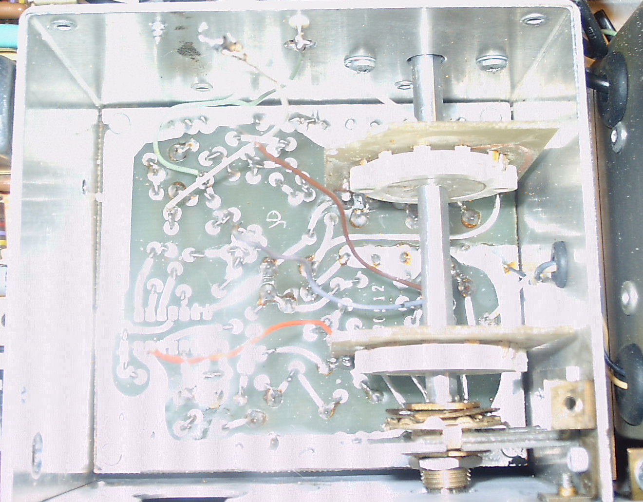
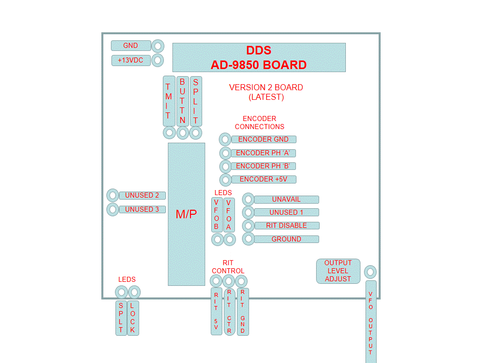
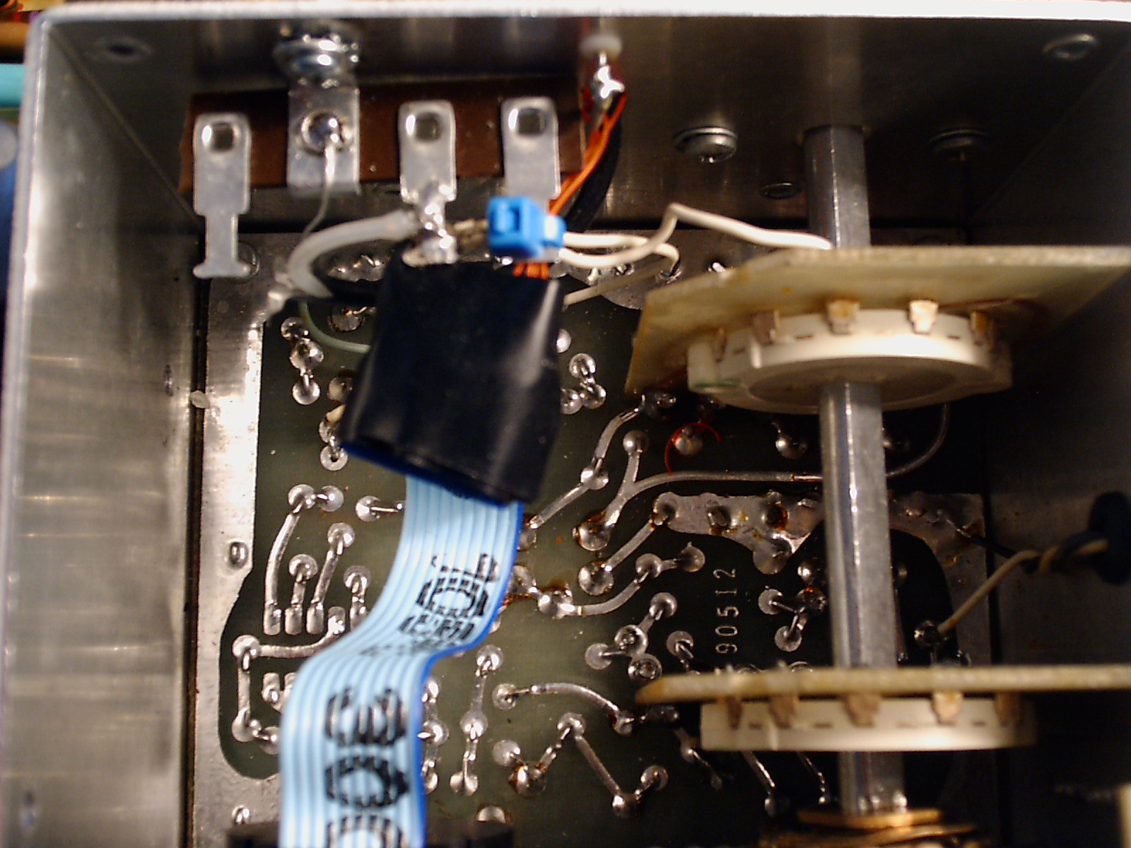
The P/C boards have been designed so that the Chinese AD9850 DDS
board can be soldered right to it. Here are pictures of the schematic, the P/C board 2 artwork, the wire connection points and a completed assembly.
3. Conversion Suggestions - Ten-Tec Triton 540 Radio
The Analog Triton (540) does not have an internal digital frequency display. So,
if you plan to undertake this conversion, you'll need some form of
digital frequency display as the PTO, the circular frequency marker and
the slide rule dial will all be gone - removed! While one could
possibly find a used external Ten-Tec digital display, I decided to
mount an Almost All Digital Electronics DFD1A device within the radio and on the front panel (more later).
a) Disassembling the
Triton
- Remove the top, bottom
and side covers. On the bottom
cover,
you'll note that the speaker connection coax is rather short
and has not been provided with a quick disconnect
plug. To save a lot of frustration and possible
subsequent damage,
just unsolder the wires at the speakers.
- Before you start the modification,
it would be wise to ensure that your radio is working, sparing
yourself a lot of headaches later. If you have received your
Triton without the octal plug in the rear panel, you'll need to strap 4
and 5 together, and pins 6,7 and 8 together. Doing so will enable
the internal PTO. Then, apply deoxit (or equivalent) to the
bandswitch contacts and rotate them back and forth several times.
- Also,
you might want to check the soldered joints on the Mixer boad where the
bandswitch contacts are soldered. If your radio has seen a lot of
use, some of these connections might be intermittent. For most of
the contacts, one can usually see the intermittent which looks like a
slight crack in the silver colored solder with a sliver of bright
copper underneath, and these may be repaired with a fine tipped
soldering iron. In some cases, it may be necessary to remove the
bandswitch shaft.
- Remove
all the knobs. The
bandswitch requires a small slotted screwdriver. Some of the remaining
knobs (like the PTO tuning) require a very small (.05)
allen
wrench - others just pull off.
- Remove the 2 bottom screws holding the front panel.
- Gently
slide the panel forward, unplugging the small connector that provides power
to the OT and the ALC lamps. Set this panel aside.
- Remove and discard the dial cord, the pointer and any thing else associated with the slide rule tuning mechanism.
- Remove
the two front panel screws holding the PTO in place. Remove the
side screws (may require the temporary removal of a circuit
board).
b) Removing the PTO and Crystal Calibrator
- Unsolder the 4 wires from the PTO (white, green, orange and brown). Remove the PTO from the radio. The green,
orange and brown wires connected to the P/C board are removed. The white wires alone as they will be connected to
the output of the DDS VFO (described later).
- Remove
the crystal calibrator from the Triton, making room
for the DFD1A circuit board. If
you decide to remove both sockets, reconnect the 2.2K resistor between
the white and green leads as it is required in the preamp circuit.
The violet wire will be used later with the digital frequency
readout board (DFD1A).
c) Pretesting and Mounting the Controller
Before installing, ensure that your DDS VFO board works
properly. Following the schematic, connect up the encoder, a
frequency counter to the output and then 12 VDC and ground.
You should see a 5.000 Mhz signal (or something very close)
which should change as the encoder is rotated. If you don't
have
a counter, your station receiver will suffice. You can even
connect it directly to your Triton at the rear jack provided for a remote
VFO.
Important Note:
The DDS VFO output level should be set as close to the output of the
Triton's PTO as possible as the Triton's circuitry was designed around
this
value. Setting the DDS VFO's output higher than this will
generate 'birdies' and needlessly increase the receiver's
background noise level. The Triton's PTO's output is approximately 1.5
Volt
peak to peak. A resistor trimmer (R5) has been provided on
the
Version 2 circuit board for this purpose. If you have a 'scope, use it to set the DDS VFO's board right on the money. If
not,
just turn R5 slowly until the radio begins to receive properly on all
bands, but no higher.
Also Note:
If you monitor the signal on your receiver, you'll probably observe a
rough, warbling note. This is normal as the OFFSET / RIT
connections
have
yet to be made and the processor's A/D converter (used for the RIT
function) will be 'hunting' a bit.
I mounted my DDS VFO in the space previously
occupied by the Noise Blanker. I removed the plug-in terminal
strips and wiring, except for the red lead which I
used to power the DDS VFO. I rerouted the coaxial cables to
effectively bypassing the Noise Blanker, and then carefully
drilled two mounting holes - one for the voltage regulator and another
diagonally across for another grounded mounting. I placed a piece
of perf board between the DDS VFO board and the chassis to eliminate
the possibility of any short circuits. I also installed a small
terminal strip to permit the installation of a series wound toroid
filter in an attempt to reduce any spurious signals from 'riding' the
12 volt line and to keep any transmitter RF out of the DDS VFO.
All-in-all, the board is very securely mounted with good ground
connections.
While
you are drilling the holes, make another one at the base of the DDS
VFO board and equip it with a grommet. This hole will be required
for the 4 offset leads and the transmit lead going to the R lead on the
Offset board.
Mount a small terminal strip on the inside of the VFO enclosure as shown here.
Using a 4-40 screw, you can 're-tap' the existing screw
hold that secures the coaxial grounds on the other side of the VFO
enclosure so that the new 4-40 screw can hold both terminal strips.
Once done, run a short piece of coax from the output of the DDS
VFO - through the small hole in the VFO enclosure - to the new terminal
strip and terminate the shield to ground. The 2 white leads will
be connected together to the coax center conductor on an adjacent
terminal strip pin. This makes for a very stable connection.
d) Installing and Connecting the Optical
Encoder
The easiest way is to place a small
metal plate (drilled for your encoder
and mounted in the existing
PTO mounting holes) on the outside
of the radio's sub-panel. Install your encoder
(finger tight) and then the front panel. If you can attach the tuning knob of your choice, and if it spins
properly - OK!
In most cases, however, you may have to mount the optical encoder on the front panel with this small
metal plate and then cut away at the sub-panel so that the optical encoder will fit (tin snips will suffice). This is what I had to do with my Triton.
- there are four (4) connections for the
optical encoder - +5VDC, ground and the two phase (Phase A and Phase B) connections, as shown here.
- using your voltmeter, double-check both the +5VDC and
ground connections on the controller board. They are located on JP-4.
The connection at the TOP
is GROUND
and the one at the BOTTOM
is +5VDC.....Make both connections. Run the wires through the small hole in the VFO enclosure and tie them to a spare lug on the previously installed terminal strip.
- connect the remaining 2 phase leads to the remaining
pins, power up the radio and turn the encoder. After you've installed the digital display you'll be able to determine if the DDS VFO is tuning in the right direction. You've a
50 / 50 chance on being right the first time.
Take
note of how the tuning acceleration algorithm works. Unlike
the PTO scenario, one can get to either band edge in a hurry.
If you would like to verify its operation before the digital display
has been installed, just connect a frequency counter to its output.
e) RIT / OFFSET Functionality
The wires from the OFFSET switch are currently connected to the Control
Board which is on the top side of the chassis. Our goal is to
reuse the wiring from the Control Board to the OFFSET control, re-routing them to the DDS VFO board underneath.
- Remove the Control Board and its paper insulator. Take note of its orientation so that it may be properly reinstalled.
- Remove the adjacent SSB Generator and the TX-RX Mixer boards, setting them and their insulators in a safe place.
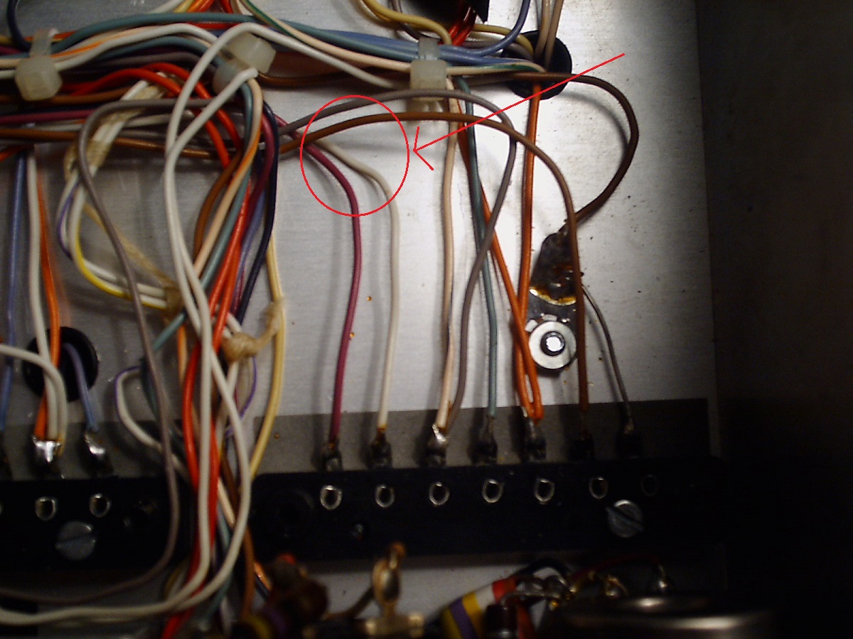
- Note the wiring on the Offset board connector. There should be
a bundle of 4 wires all tied together that run from the Offset control.
They are colored brown, white, violet and gray. The brown, white
and violet leads are connected top the Offset potentiometer (12K), and
the gray wire enables the OFFSET when the radio is in the receive mode.
- Carefully remove these 4 wires
from their lugs on the Control board and move the whole wire forum back
so that you can reinstall the Control Board and the SSB Generator.
Don't remove any other wires.
- Push these wires through the previously drilled grommeted hole for subsequent connection to the DDS VFO board.
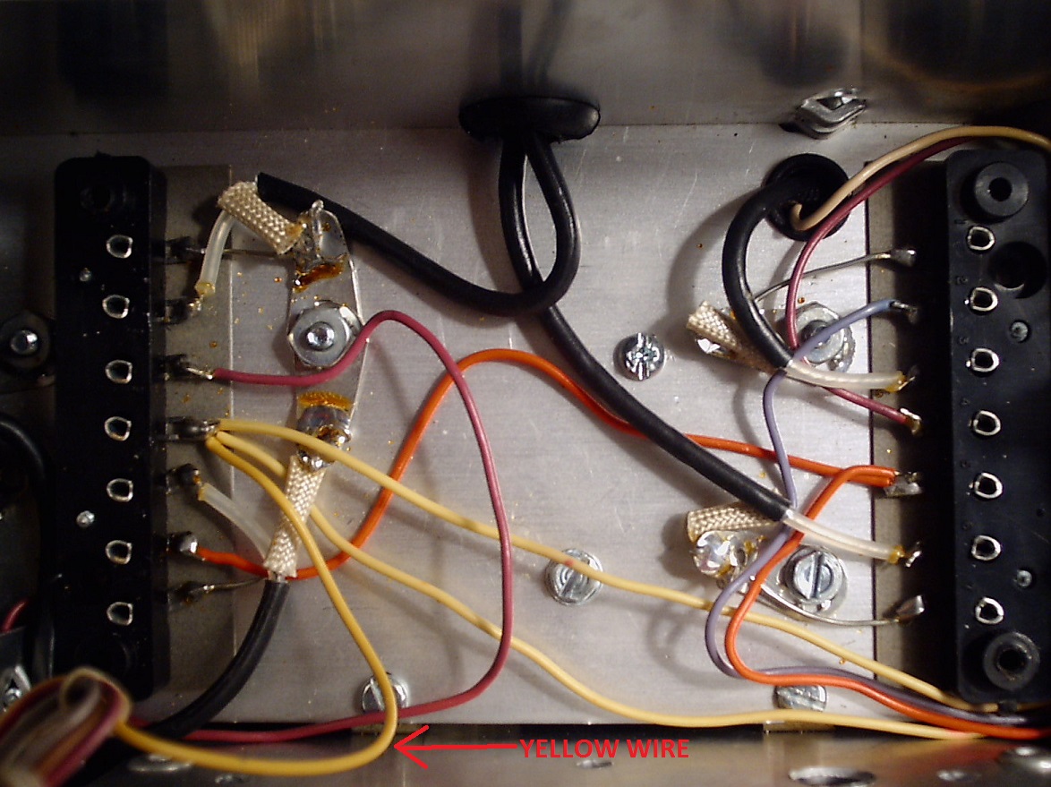
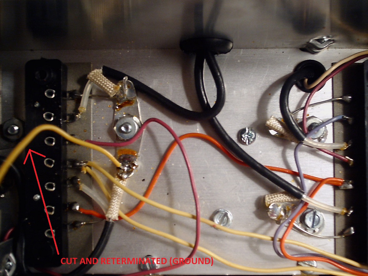
- Examine the wiring bundle from the Offset control and note the yellow wire and where it is connected
on the underside of the TX-RX Mixer board. This wire goes to the T lead
and its purpose is to disable the OFFSET when the radio is in the
transmit mode. Carefully remove it from its connection on the
TX-RX Mixer board and connect it to a nearby ground lug (as shown here).
- Place your meter on the gray wire and verify that it goes to ground when the OFFSET is enabled (pulled out). It's very important that the proper yellow wire is moved as the T lead voltage will destroy the processor chip.
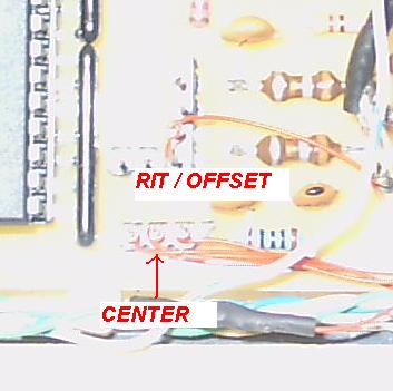
- On
the DDS VFO board, connect the while wire to the RIT CTR, the brown
wire to RIT 5V, the violet wire to RIT GND, and the grey wire to RIT
ENABLE, as shown here.
- Connect
the TMIT on the DDS VFO board to the R lead on the Control Board, as
shown here. Once done, replace the insulator and then the TX-RX
Mixer board.
f) Installing the Digital Display Controller - Repurposing the Crystal Calibrator Activation Switch
I used an AADE DFD1A
digital display board mounted in the space
vacated by the crystal calibrator and the LCD display mounted on the
Triton's sub-panel. First, remove the two circuit boards on the
other side of the chassis and carefully drill two holes for the 4-40
screws that will support the DFD1A circuit board. Install a piece
of perf board (Radio Shack) between the two stand offs created by the
4-40 hardware.
Assemble the DFD1A
board using the instructions provided in the kit, mounting the pin
header and other wiring connections as well as the LCD contrast and
TXCO trimmer resistor on the component side of the AADE provided
circuit board. The board is assembled this way to provide access
to these points after the DFD1A board has been mounted on the perf board. I used simple wire straps to hold it in place.
The DFD1A
makes for an exceptional digital frequency readout. However, when
connecting it up to the Triton 540, a switching mechanism needs to be
provided to 'tell' the counter if it should be 'counting' up or down.
Rather than drilling another hole in the radio's front panel, I
opted to use (repurpose) the existing push / pull switch on the RF gain control,
the one that was used to activate the crystal calibrator.
As shown on the schematic, this switch provides 12 VDC to activate the
calibrator, but the DFD1A board requires a grounded connection.
The actual switch connection on the rear of the RF Gain control
has a 12 VDC tie point (4 wires) on one lug,
and a voilet wire on the other. This is the violet wire that runs
to the previously removed cryatal calibrator board. The 12 VDC
tie point needs to be removed and a ground substituted.
Carefully unsolder all 4 wires from the switch, solder them together and cover them with 2 layers of heat shring tubing.
Then connect a wire from the spared terminal to ground, as shown here.
Verify with your meter that operating the switch provides a solid
ground on the violet wire, and then connect the violet wire to the
appropriate point on the DFD1A board. Connect the power and
ground leads from the DFD1A module to the 12 VDC connections on the DDS VFO board.
I used the 'Biggie' display provided by AADE. It fits nicely in
the narrow space between the chassis and the front panel. After
carefully measuring and drilling the holes, I mounted the display with
4-40 hardware.
Before mounting the display, I
wired it with 30 gauge wire. Since the space between the chassis
and front panel is mininal at best, I was not able to use pin headers.
Rather, I soldered the 30 gauge wire directly to the holes in the
LCD in which the pin headers are normally inserted. Once the
wiring was done and double checked, I provided several layers of
plastic tape to guard against shorts and then mounted the LCD.
The wiring back to the DFD1A board was run through a newly
drilled - grommet equipped - hole in the front of the chassis.
Using a short length of RG-174 coax, connect the outout of the Triton's
VFO to the input of the DFD1A counter through a 100 pf ceramic
capacitor.
Hold off on reinstalling the front panel as it needs to be reworked a bit.
Hint:
It's not necessary to ground pins 10, 9, 8 and 7 on the LCD
board. A ground connection between pin 1 and pin 5 will suffice.
g) Reworking the Front Panel
First, remove the plexiglass panel and then 3 incandescent bulbs. At the very least, a function button needs to be installed on the front
panel to switch VFO's, activate / deactivate the SPLIT mode, and so
forth. Additionally, optional status LED's may also be installed,
but I dfecided not to install them at this time. This is a very
tight front panel arrangement, not at all like the rather spacious Omni
series.
Were even the smallest push button switch installed flush with the
front panel, a corresponding hole would need to be made in the chassis
to accommodate the wiring. So, to simplify matters, I just
removed the OT LED and drilled out the opening just a bit to
accommodate a miniature Radio Shack normally open push putton switch (Crazy glued in place).
Connect one lug on this switch to ground and the other to the
trace on the P/C board that goes back to the OT lead. DO NOT CONNECT IT TO THE 12 VDC TRACE.
Next, remove the OT TR board and snip the OT-LITE wire right at its
connection lug. Remove both the Control and SSB GEN boards so
that this lead can be run (through an existing plastic grommet) to the
DDS VFO board on the other side of the chassis where it will be
terminated on the button lead, as shown here. Once done, reinstall the insulators and the boards themselves. Don't turn the power on yet.
h) Reinstalling the Front
Panel
Ensure that the leads for the optical
encoder are run
properly (no kinks or snags). Move the front panel close to the
sub-panel and
connect
the 3 wire plug that operates the ALC and OT lamps and then place the
panel in place, securing it with the previously removed bottom screws.
Using your meter, verify that the push button - when pushed -
grounds out the button terminal on the DDS VFO.
i) Testing the
Controller
- turn the radio on again and note the
digital display. It should show a frequency close to the low
end of the band. Then turn it off again.
- Turn the radio on and vary the OFFSET / RIT
control. If the
OFFSET control works in the proper direction.
- Verify that the FUNCTION button - when briefly tapped
- will switch from one VFO to the other.
- Verify
that the radio transmits properly in the SPLIT mode.
- Complete the alignment of the DFD1A by adjusting the top mounted resistive trimmer.
4. Commands
When powered up, both the A and the B
VFO
will
be set to the lower band edge, that is, 7000, 3500, 1800, 28000 (etc).
VFO A will be enabled. The user may then tune with
VFO A in
the normal manner, and VFO A will be used for transmitting.
If
the RIT (OFFSET) switch is activated, the receive frequency will vary
based upon
its setting; the transmit frequency will not change. When
the
OFFSET is turned off, the original frequency will be restored.
To switch to VFO B, depress (tap) the FUNCTION button briefly, and the
system will be using VFO B. The frequency previously stored
in
VFO A will not be changed.
Note: if you have wired up the optional LEDS, the LED for
either VFO A or VFO B will be illuminated.
To enter the SPLIT mode, just tap the FUNCTION button
twice (a short followed
by a longer tap - like a
' A' in CW) and the radio will enter the
SPLIT mode. The on-line
VFO
will control reception, while the off-line VFO will control
transmitting.
Note: if you have wired up
the optional LEDS, the SPLIT LED will be illuminated.
To exit the split mode, tap the FUNCTION button twice (another
short - long tap sequence) and the
radio will revert to the normal mode. The contents of the
on-line
VFO will be copied into the off-line VFO.
To
LOCK the system at any point, just hold the FUNCTION button down
for 2 seconds and the system will be LOCKED, and cannot be changed
until UNLOCKED. To unlock the system, just tap the FUNCTION button - and that's it! While LOCKED, the RIT control will work.
Note: if you have wired up
the optional LEDS, the LOCK LED will be illuminated.
An
optional button
has been added dedicated
to the SPLIT
function. Tap
it one time and the SPLIT function is active. You can then
use
the main button to switch between the VFO's. Tapping the
SPLIT
button again will disable the split function and map the on-line VFO
into the standby unit.
To store the last used frequency before powering down, operate the LOCK function,
release
the button and push it again within
one second.
If you have equipped the LED's, they will all flash 3 times
to
indicate that the frequencies (VFO-A, VFO-B and the split function)
have all been stored in flash memory and will be available whenever the radio is next
powered up.
Note:
The instruction manual for this processor states that
the flash memory can be updated just 10,000 times, so you might want to
use this function frugally. If you want to disable it, simply
ground the FLASH INH lead (see the schematic).
5. How the Software Works
- The
30,000 Foot View - click here
6.
On-the-Air Results
a) Receiving
The P/C board is mounted
in the rear of the chassis, with no shielding and with rather long
leads for the Encoder, Offset and Push Button controls, and it works well for me.
Note:
One way to cut down on spurious mixing products is to follow the
instructions in the service manual to adjust both R23 and R2 on the oscillator / mixer board. Perform
the adjustments shown in Step 3 and in Step 7 (Mixer Balance).
With an antenna connected and the preselector peaked, there are a few detectable narrow banded (200
to 300 khz spurs). The
louder spurs are asterisked.
- 10
Meters (B) - 28978*
khz.
Note: This 10
meter spur (28987 khz is quite loud) is a known Omni issue. To tune this frequency, set
the bandswitch to the 29 Mhz position and tune downward. Check the
service manual for more information.
b) Transmitting
Several
SSB QSO's were made on 40 meters, and the reports were comparable to
what one would expect from a PTO equipped Triton - generally very good.
Both the SPLIT and QSK functions work
properly on CW.
8. Other Concerns /
Considerations
If the user decides to tune up the
antenna to make
a QSO
(say, answering a CQ), and if the antenna SWR is too high - the power
supply circuit breaker will trip. Since the DDS board is
powered
by the same supply, the desired frequency will be lost when the breaker
is reset. This
is one of the drawbacks of using DDS in lieu of
the analog PTO when the DDS is
powered by the current sensing power supply.
Three solutions are possible.
- The DDS board could be powered separately -
say by a wallwart supply -
and left on all the time. This way, should the Triton's power
supply trip out, the desired frequency information will be retained on
power up. Gauche? - yes, but workable.
- If
the AIRPAX (or equiv) circuit breaker used to safeguard the radio's
finals were to be installed in the Omni proper, then the DDS VFO could
be powered on the 'line side'. This way, the circuit
breaker's
tripping would not cut the power to the DDS module.
- Alternately, the operator may gradually increase output
power (using the drive control) when tuning up to an antenna.
9. Using an External DDS VFO Controller
- Front, Side, Rear Views
Those reluctant about digging into their radio to mount the
DDS VFO P/C board, encoder (etc), may opt to build the whole thing in a
separate enclosure as shown in the above pictures. As you'll
note, the prototype unit has 4 unmarked LED's across the top (VFO-A,
VFO-B, SPLIT and LOCK), a red and a black push button, the tuning knob
for the optical encoder itself, and the RIT control with an activation
/ deactivation switch.
The rear panel shows
the power connector, the VFO output and a third phono jack into which
the transmit signal from the radio is to be plugged, as was done with
the internal modification (R lead) that was just described.
The black button
is the multi-function unit that lets the user switch VFO's, operate
split and lock the dial. The red button is just a one press
access to the split function.
Note: The unit shown here worked very well with both my Ten-Tec Omni and Drake TR7. Another ham is using it with his Corsair 1.
Over Voltage Protection
Should the pass transistor fail on your
power supply, the output voltage can quickly rise to 25 volts or so,
wreaking big time havoc with your radio's solid state devices.
A
simple way to guard against such a failure is to place a zener diode in
the radio on the other side of the fuse so that of the voltage should
rise to 14.8 volts (for example), the zener will conduct and draw
enough current to pop the fuse first. I used a 1N6275AG purchased
from Mouser and placed it in the circuit as
shown here
.