Dual Digital DDS
VFO for Ten-Tec Omni, Argosy, Corsair, Drake TR-7, Heath SB-104(A) and
Other
Display Equipped Transceivers Using a
5.0 - 5.5Mhz VFO
- Ten-Tec Radios - Application
1. Introduction - provides frequency changes in 10 hz. steps, is drift free and is and is rock solid.
This
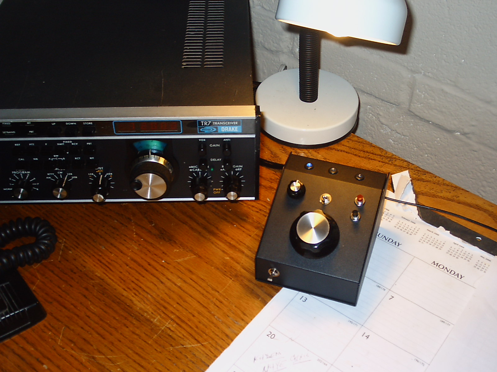
webpage describes a standalone, PIC processor based DDS VFO designed for the reasonably experienced homebrewer. It can be mounted within a
Ten-Tec, Drake (or any other solid state radio that uses a 5.0 - 5.5
Mhz VFO) or housed in a small metal enclosure.
The Dial FREQUENCY
LOCK and EEPROM
storage of the last used frequency features are included. Please review
the whole web page if you are interested in building this VFO.
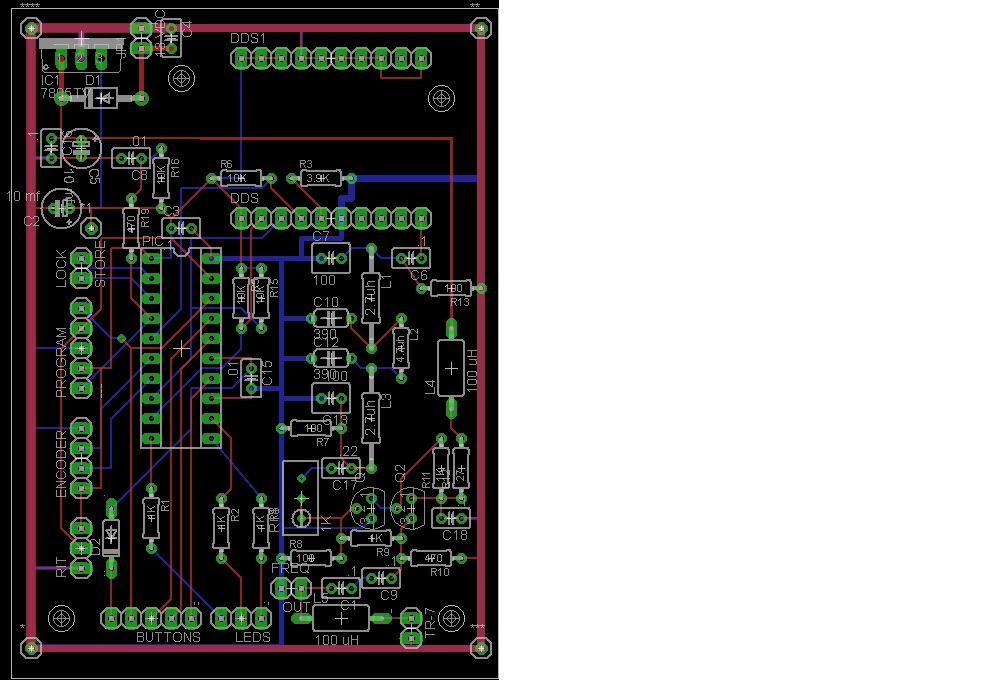
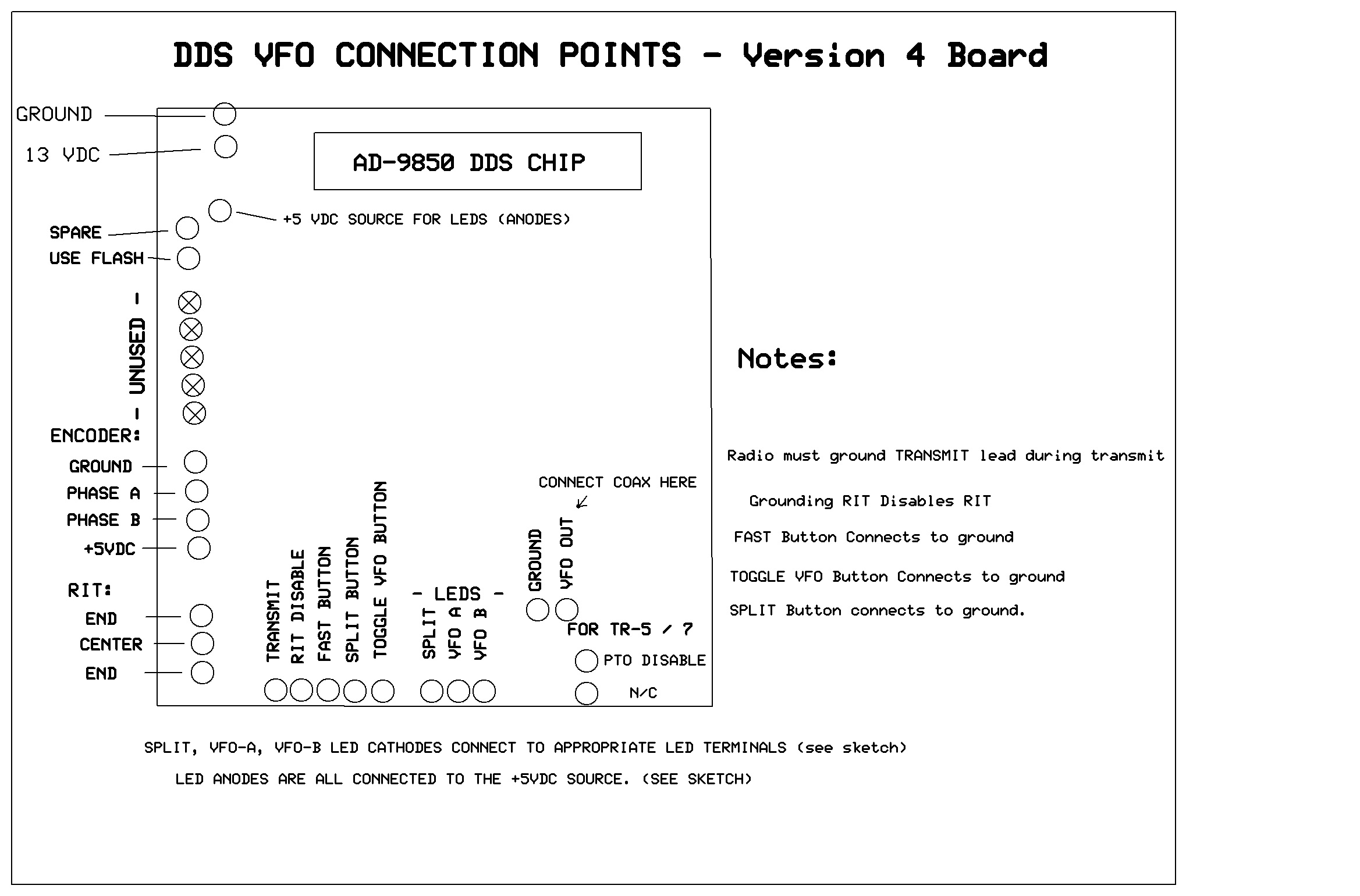
The latest version (4) Version 4 board allows the on-board mounting of the
100 mh inductor (L5) used in the TR-5 / TR-7 applications.
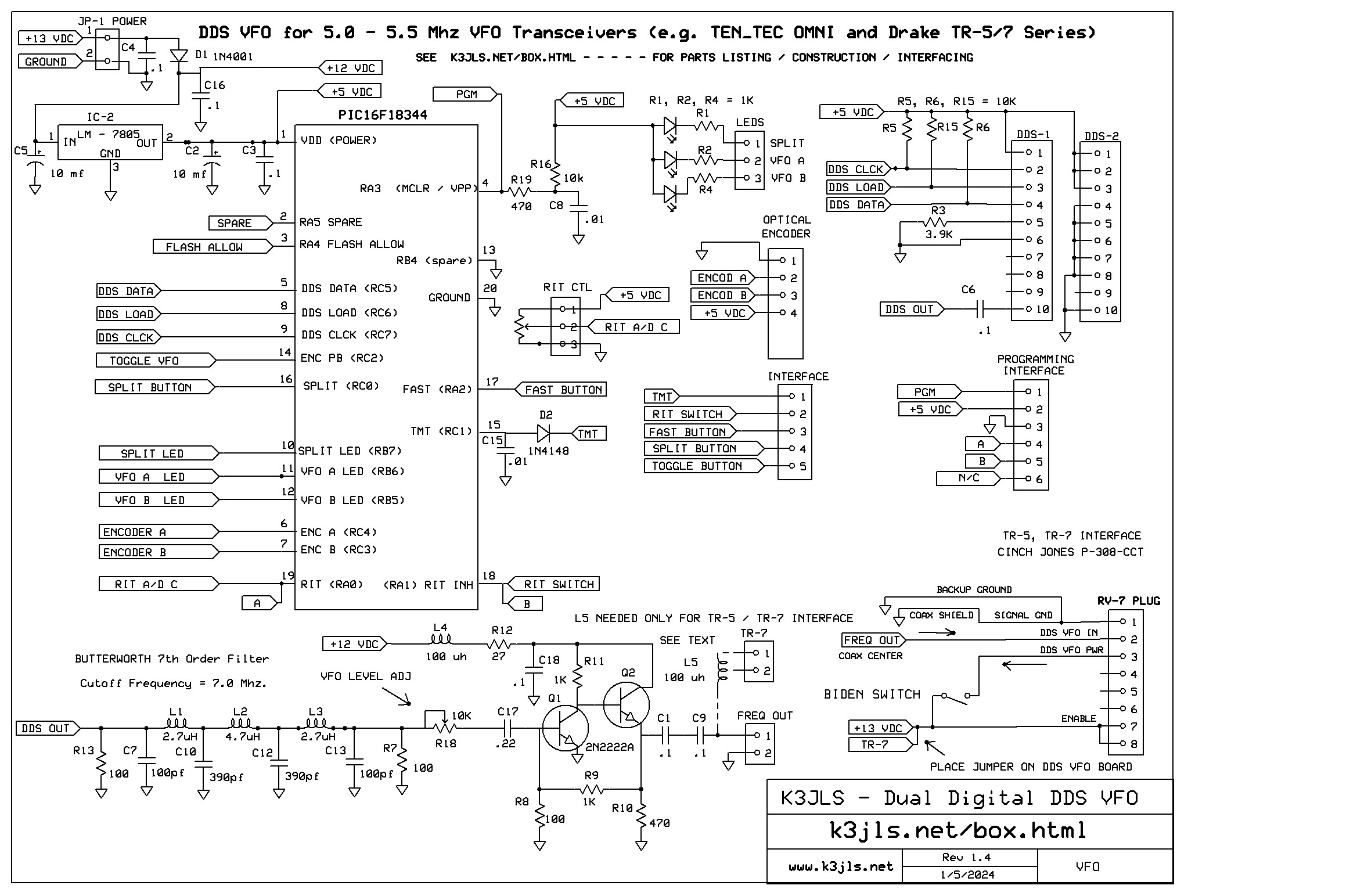
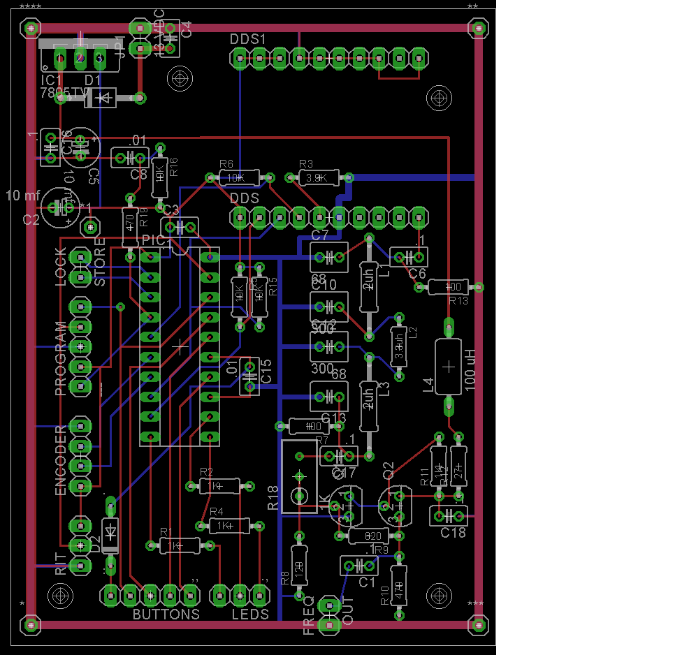
Here's a schematic of the Version 4 PCB, the Version 4 PCB artwork, connection points, and a parts list.
2.
How It Works - 30,000 Foot View - All-in-all, the program is very 'well behaved'.
The
AD9850 is a highly integrated device that uses advanced
DDS technology coupled with an internal high speed, high
performance D/A converter and comparator to form a complete,
digitally programmable frequency synthesizer and
clock generator function. The
AD9850 generates a spectrally pure, frequency/phase
programmable, analog
output sine wave. The AD9850 board comes with an integral 125
Mhz
clock oscillator and a 7th order eliptic filter with a 42 mhz cutoff.
To further
eliminate the possibility of spurious signals,
an additional 7th order Butterworth filter with a 7 mhz cutoff
frequency has been provided on the printed circuit board,
all followed
by a 2 transistor amplifier with an adjustable and stable output of up
to 4 vac.
This DDS VFO
has a fixed operational range between 4.950 and 5.550 Mhz.
The PIC sends serial commands to
the AD-9850 to update the frequency. The program runs in a loop, constantly checking the optical
encoder. When either the Toggle or Split buttons
are depressed, or when a transmit signal is sent by the served radio,
demand interrupt routines are called to service them. A timed
interrupt routine is used for RIT (50 ms).
The software
driving the AD9850 provides 2 VFO's (A&B), split frequency
capabilities, Receiver Incremental Tuning (RIT), (optional) power up
retrieval of
the last used frequency and encoder locking.
3. Building the Board
- Construction
Suggestions for All Radios - Parts List
Use a grounded (3 wire),
fine tipped, ESD safe soldring iron to build up this kit. Some kind of magnifying
glass would also be advisable. Consider using
30 gauge solid conductor wire and an appropriate wire
stripping / wrapping tool. It's manageable and works very well.
Standard components from
reputable suppliers (like Mouser) are used. The only
exception
is the DDS unit which is available on eBay or on Amazon (very fast shipping and excellent return options). This
software has been written for the
AD-9850
DDS only. Optical
encoders are usually available on eBay, as well. Try to get one
with a 128 to 256 quadrature pulses per revolution.
They're relatively inexpensive.
When soldering the components to this
board, use a fine
tipped iron and apply only as much solder as is needed to make the
connection - nothing more. Remember the Bryl Cream commercials from the '50s? A little dab will do ya! Give the solder ample to time to
fill
the space between the wire and the PCB plated hole. Before soldering the
components double check to ensure that you have the right one.
If you make a
mistake and solder in the wrong or a defective component, don't panic. Almost
all components can be harmlessly removed without damaging the
PCB, as described below.
Use your diagonal cutters to snip the component on the top side of the board. Next, use your needle nosed pliers to grip the
legs (one after the other) of the severed component, turn the board
over and then apply heat from your soldering iron, after which the
parts
will easily pull out. There will probably be
some
solder residue which will inhibit placing the proper part.
The
holes will need cleaning out.
To do this, place one
lead of a scrap component (like a resistor or capacitor) on either side
of the hole and heat the wire as close of the board as
possible
without burning it. Very soon, the wire from the scrap componentd
will begin to slide thru the hole. If the part drops all the
way
thru and can be freely turned, just snip off the excess lead on the
other side of the board and you're done with this hole. You may
have to do this several times with several scrap components to achieve
the desired result. Don't fret -
it's dooable. Properly done, they'll be no significant
evidence that a component was replaced.
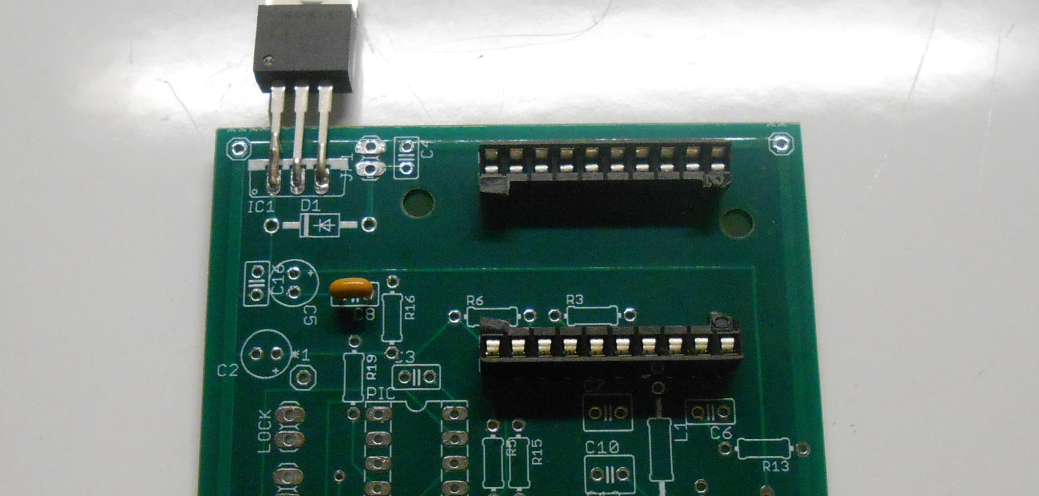
1. Ensure that you are mounting the
components on the silkscreened side of the blank
printed circuit board.
2. Mount the first 20 pin integrated circuit socket (for
the
PIC processor) - the
notch points to the top.- Note: The
next steps will ensure that the AD9850 mounts properly on the
board when it is installed later..............and.....that it may be easily replaced later should it ever fail. It
would be very difficult (but not impossible) to unsolder a defective
AD-9850 unit from the board....and then reuse the board were the
AD-9850 initially solderd in.
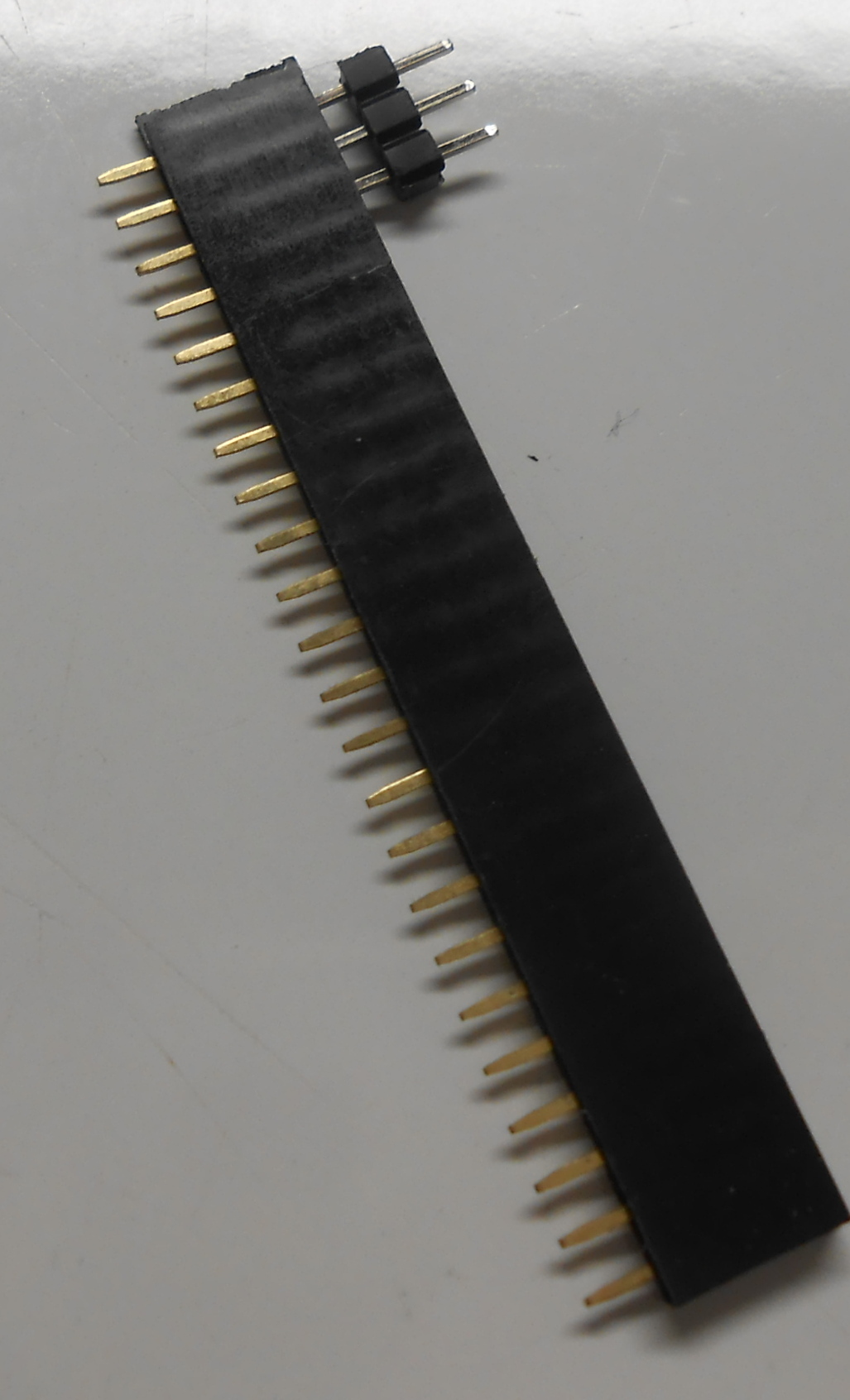
- CAREFULLY cut the second 20 pin socket in half forming a socket for
the AD9850
- Remove the AD9850 from its static protected foil enclosure.
- Ensure
thet all the pins on the AD9850 run in a straight line and are equally
spaced (needle nosed pliars will ensure their 'straightness).
- Gently
insett each of the socket 'halves' onto the AD9850 pins, starting with
an end pin and then gradually progressing until each socket half is
fully seated. - pintinginward - as shown......
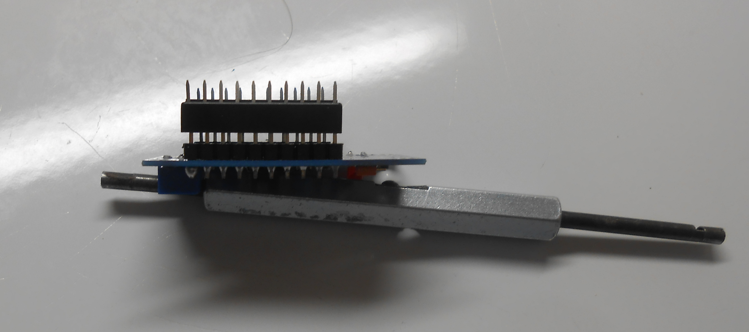
- Mount the newly socketed AD9850 on the PCB - the red led will go towards the center
and the variable resistor on the right side of the board.
- When you are satisfied with the positioning, carefully solder each of the 20 socket pins with the AD9850
installed in them.
- Remove the AD850 from the newly soldered board and put it
back into its
static protective packaging.
3. Install
the 5 volt regulator - LM-7805. Leave enough 'slack' in the
leads
to allow it to be bent back flush with the chassis (heat sink) on which
it is to be mounted with heat
conducting grease.. Proper heatsinking is vital for consistent RIT operation.
4. Install reverse polaity protection diode D1 (1N4001 - or equvv)
Note
the polarity shown on the printed circuit board.
5. Install diode D2 (1N4148) -
transmit interface -
buffer between the PIC and the transmitter transmit signal. Note
the polarity shown on the printed circuit board.
6. Install nine (9) .1 mf capacitors (C1, C3, C4,
C6, C8, C9, C16, C17, C18) - C8 is a decoupling capacitor whose value was just increased on the latest PIC1618344 data sheet.
7. skip this step.
8. Install one (1) .01 mf capacitor (C15)
9. Install the 100 uh inductor (L4) - If you plan to connect the DDS VFO to a Drake TR-5 or TR-7, install L5.
10. Install 5 (five) 1K, 1/4 watt resistors (R1, R2,
R4, R9, R11)
11. Install 1 (one) 3.9k 1/4 watt resistor (R3)
12. Install 4 (four) 10 K, 1/4 watt resistors (R5, R6, R15, R16)
13. Install 1 (one) 27 ohm, 1/4 watt resistor (R12)
14. Install 2 (two) 470 1/4 watt resistors (R10, R19)
15. Install 1 (one) 100 ohn, 1/4 watt resistor (R8)
16. Install the 10 K trimmer resisor (R18) - used to adjust the DDS
amplifier output level - place the adjusting screw at the bottom of the PCB. - max stable output possible is 6.0 VAC,
peak-to-peak.
17. Install 2 (two) 100 ohm 1/4 watt resistors (R7,
R13)
18. Install 2 (two) 390 pf capacitors (C10, C12)
19. Install 2 (two) 100 pf capacitors (C7, C13)
20. Install 2 (two) 2.7 uh inductors (L1, L3)
21. Install 1 (one) 4.7 uh inductors (L2)
22. Install 2 (two) 10uf 25 volt electrolytics (C2, C5) -
observe the polarity
23. Install 2 (two) PN2222A (or equivalent) transistors (Q1,
Q2)
Important Suggestion - when soldering the pin headers (next step), you might first want
to first place them in a spare integrated circuit socket or in a female header pin set (usually available on eBay). This
way, the heat
of your soldering iron will not melt the plastic and cause the pins to
seat unevenly. I've soldered hundreds of pins this way. It always works.
24. Install pin header connectors at the following points:
- AD9850
DDS Assembly (purchase from eBay, Amazon, etc.). A fully assembled unit with a
timing crystal and an output filter costs around $20, and sometimes
even less - shipped
free to
your home. Amazon also sells them; they cost a tad more, but very quickly shipped. This device
will plug right into your board and can easily be replaced, if
necessary. They've proven to be very reliable.
- Optical
encoder w/Knob -
(eBay is an excellent source), e.g:
- Bourns
ENJ1A-B28-L00128L
encoder (purchased on eBay for $21) with a pulse rate of 128
quadratures per revolution will generate 2.5 khz per complete
revolution, a
- US
Digital S1-360 encoder (also purchased on eBay for
$14) with a pulse rate of 360 will generate about 7.2 khz per
complete revolution, a
- US
Digital S1-250 encoder ($14 shipped - on Bay) with a pulse
rate of
250 pps will cause a 5khz excursion per dial revoution, etc.
- Since hams have their own tuning
rate preferences and will probably select their own encoder, I replaced the interrupt based tuning
acceleration algorithm with a simple FAST
button (or switch).
- Light
Emitting Diodes (3)
- Mouser
: 941-C503BBCNCW0Y0452 - or equivalent, for: VFO A,
VFO B and SPLIT
- SPST
Push Buttons - - for: VFO Toggle, the SPLIT Function, and
for FAST Tuning Select (hold for fast tuning)
- Ebay is an excellent source
- SPST
Switch - activates the RIT
- Ebay is an excellent source
- 20K (or so) linear taper potentiometer (with knob) which
serves as the
RIT control.
- Mouser: 652-PTD901-1015FB203
4. Testing the Board - you should be working in a static free
environment
Before
installing the PIC
processor and before
installing
the AD9850 DDS board - Measure
from the heat sink of the voltage regulator and verify that you have
ground on pin 20 of the PIC processor socket and on pin 6 of connector
DDS-1 and on pins 4,5,6,7,8,10 of connector DDS-2.- Apply
13VDC to JP-1, and verify that there is an approximate +5VDC on pin 1 of the PIC
processor, on pin 1 of connector DDS-1 and on pins 1,2,3 of connector
DDS-2.
- Verify approximately 13VDC on both sides of
inductor L4.
- Remove power from the PCB.
- Install the pre-programmed PIC (notch goes at the top) in
the previously installed DIP socket.
- Carefully (once again) remove the AD9850 from its static
free packaging
and install it on the board ensuring that all the pins are seated
properly and that the RED
LED is in the center
of the board.
- Apply 13VDC as you did before, and the RED LED should
light.
- Connect a frequency counter to the FREQ OUT pin and
- Adjust R18 until you see an approximate 5 Mhz signal on
your 'scope, or hear it on your radio (it may sound a bit warbly
because the RIT pot has not yet been connected). R18 will
be adjusted for the proper output level when the VFO is connected
to your radio. If R18 is installed with the adjusting screw at the bottom of the board, turning the screw clockwise increases the output level.
- Remove the power and install the DDS VFO either in a stand
alone enclosure (highly recommended), or in your radio proper.
- Connect
the power source, the optical encoder, the RIT control, and the TOGGLE,
SPLIT, and FAST buttons using 30 gauge wire and a wire wrapping tool.
- Verify that both the optical encoder and RIT control tune
in the proper direction. If not, just reverse the connections.
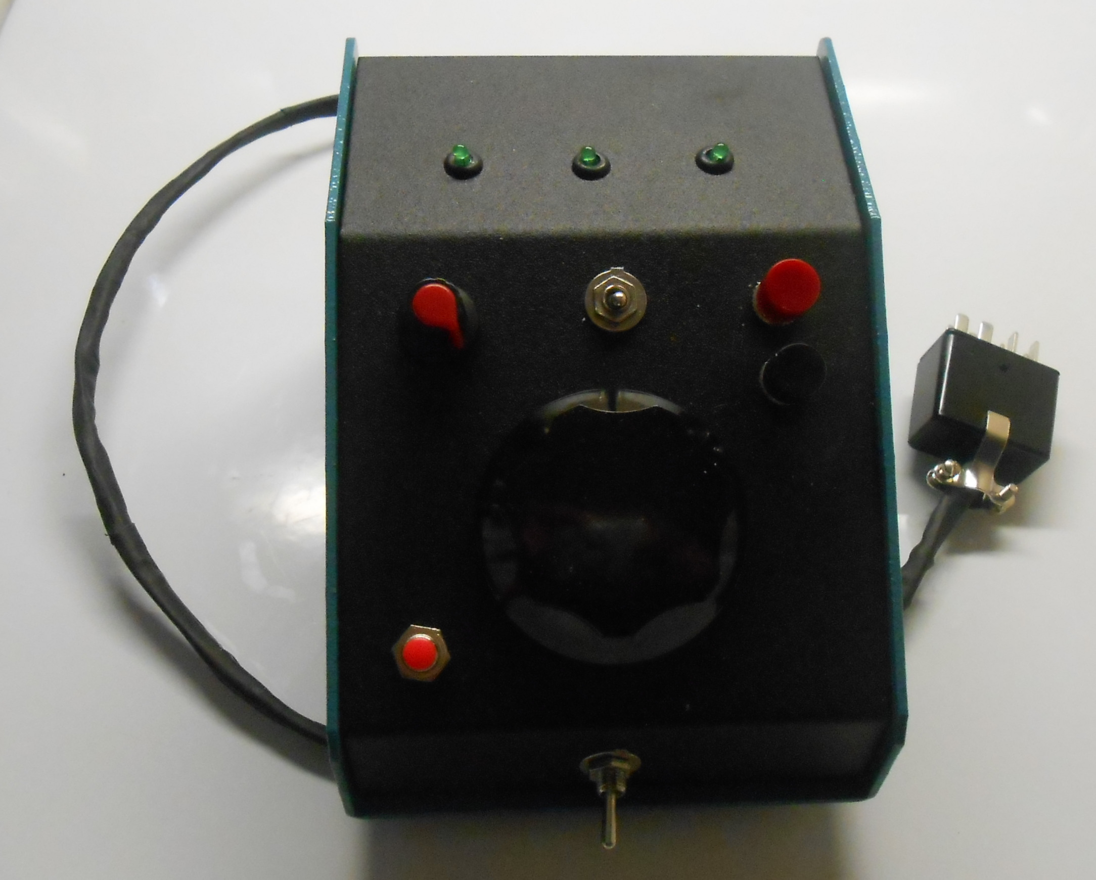
- If you are building the DDS standalone, you'll need a
suitable enclosure. Both Mouser and Digikey
have some nice sloping ones (recently
constructed example).
5) Drake TR-5 / TR-7 - Application
a) Building the Enclosure
This
enclosure can be used with either the Drake TR-5 / TR-7, with
Ten-Tec radios, with the Heathkit SB-104 - 104A - and / or with other units that have a 5.0 - 5.5 Mhz VFO
/ PTO. The only significant differences will be the how the unit
interfaces with the radio. I used a 2 piece, sloping panel enclosure from Mouser
Electronics. With this enclosure all the
connections to the PCB, optical encoder, RIT pot, switches, push
buttons, input / output and power connections can be made on the
sloping panel potion itself. The PCB is mounted herein, as well. Here are the steps that I
took:
i) Hole Drilling / Component Mounting - Measure Twice ---------- and Drill Once- determine where you want the controls and the LED's and drill the holes to suit your preference,
- install
the TOGGLE, SPLIT, FAST push buttons, the BIDEN and RIT switches, the tuning encoder, the 20K RIT potentiometer,
the 3 LED's, and - on the rear of the enclosure - the transmit RCA phono jack and the female 12 VDC
power connector (for Ten-Tec and similar radios) - the Drake TR-5
/ TR-7 application needs a grommeted hole for the connecting cord.
- drill
a hole and mount a ground tie point near the bottom of the chassis.
This will be used to terminate the backup ground wire from the cord
and serve as a tie point for other ground wires.
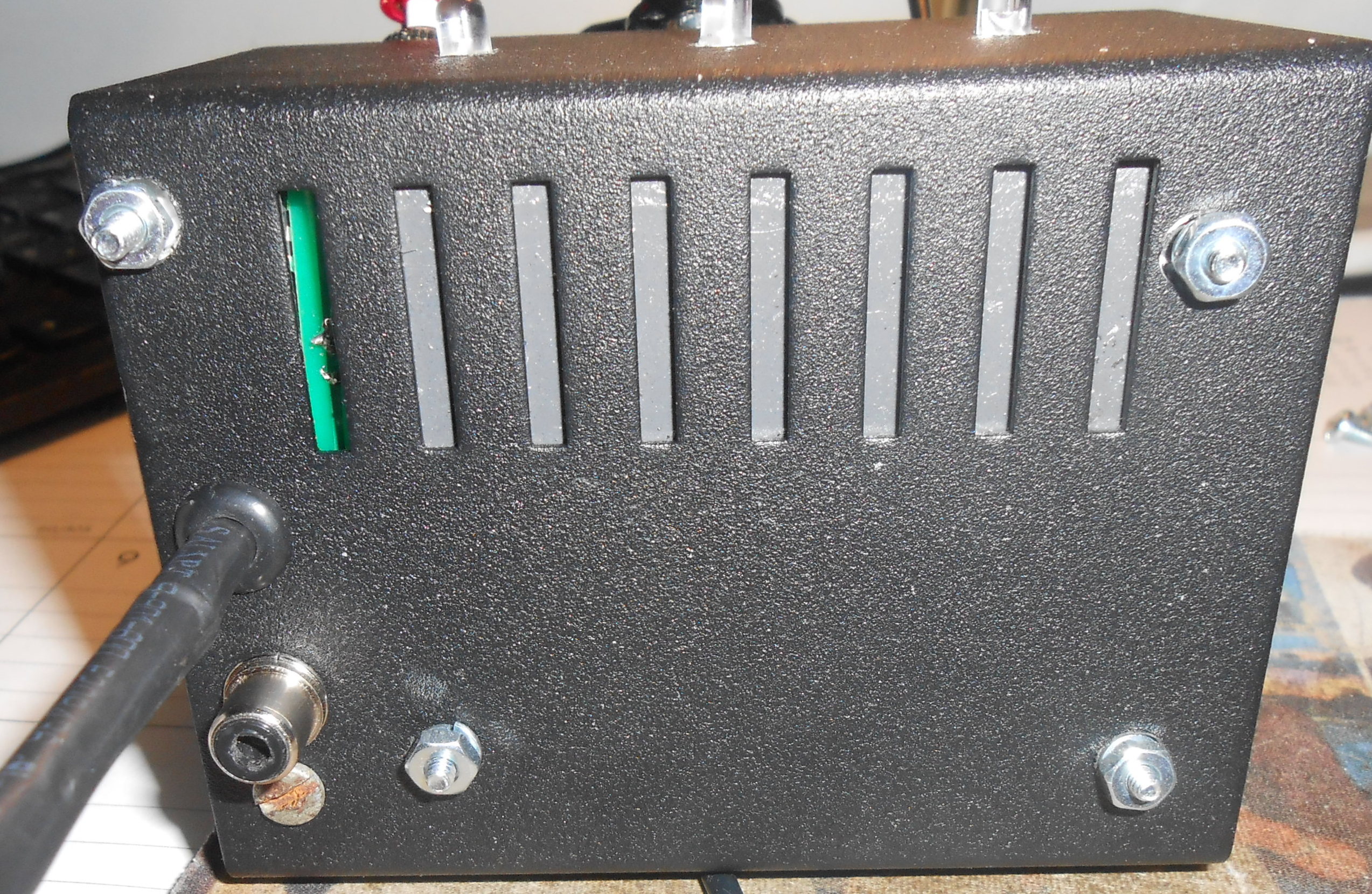
- mount
the completed and tested PCB on the rear panel using 4-40 hardware.
It will be necessary to insulate the back of the PCB to avoid any shorts. I used a hunk of stick-on floor
tile to accomplish this although a piece or non conductive perf
board would work just as well,
- carefully drill a hole to heat sink the LM-7805 voltage regulator
and use a dab of heat sink compound to secure it to the chassis.
Without the chassis heat sink, the LM-7805 may fail,
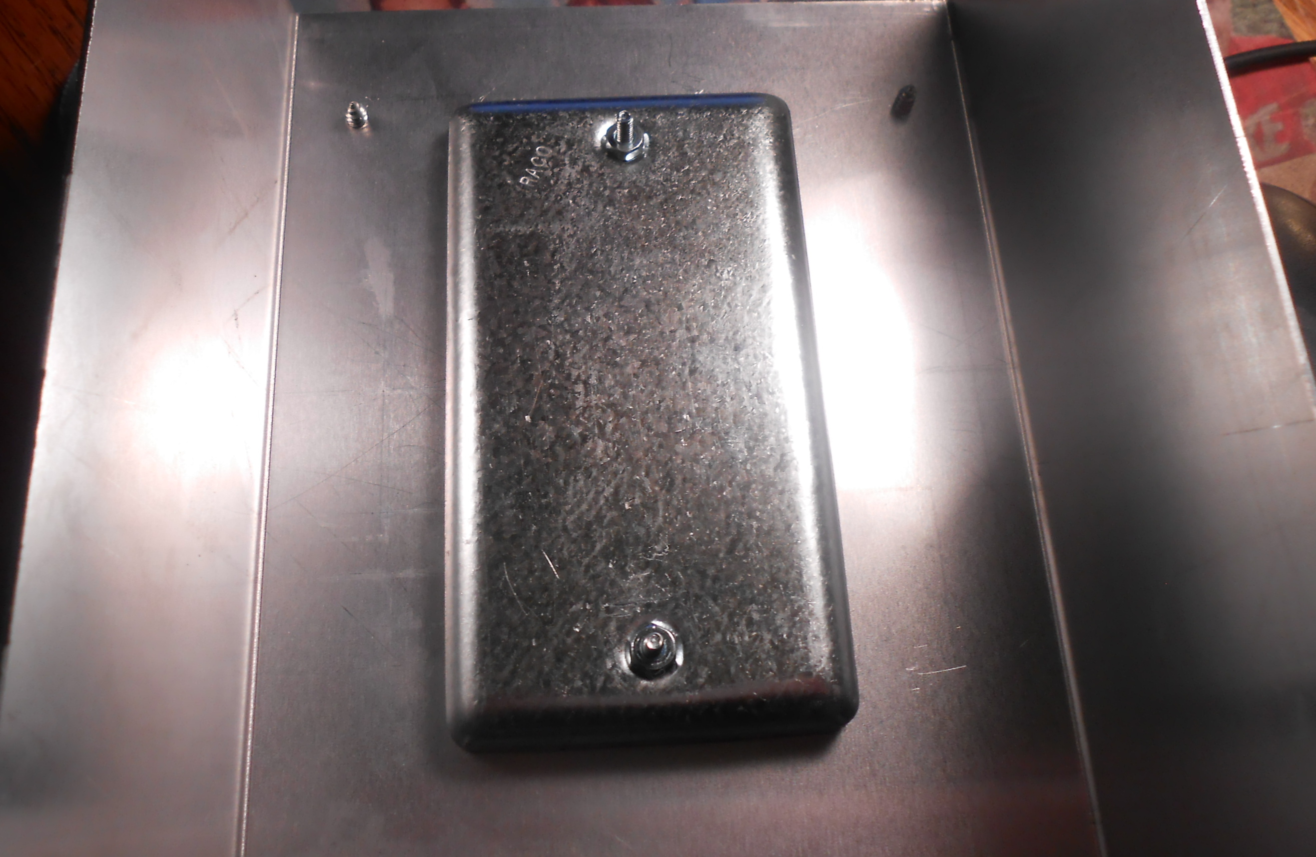
- This particular unit was weighted
down internally with 3
steel outlet covers (Home Depot). It rests very securely on my
desktop.
- If this enclosure is being constructed for Ten-Tec and similar radios, advance to Wiring the Box.
The LM-7805's ground tab must be connected to
the box or chassis to ensure good thermal conductivity.
- Also,
if the LM-7805 is not properly 'heat sunk', its output voltage may
drift to the point where RIT accuracy could be degraded - - as RIT uses
the processor's internal A/D converter.
b) Preparing the Connecting Cord - for the Drake TR-5 / TR-7
As an external
VFO for your Drake TR-5 / TR-7,
refer to the schematic for the extra wiring. You'll need a
Cinch-Jones Plug P-308-CCT (eBay),
another 100uh
inductor (L5 which mounts either within
the P308 plug (between pins 2 and 7) or preferably on the PCB), some RG-174
coax and stranded wire. When done, the DDS VFO plugs into
the TR-5 / 7's Remote VFO connection and is powered by the TR-5 / TR-7 (RV-7, pin 3) which is always 'hot' when the TR-5 / TR-7 is powered up..
When the Biden switch is operated, +13 VDC (fom the radio) is sent to
connector JP-1 - pin 1 and - thru inductor L5 - to RV-7, pin 2 -
disabling the internal TR-5 / TR-7 PTO,
(the RV-7 external VFO
would disable it this way). At the same time, DDS VFO
is enabled by the same +13 VDC. Inductor L5 ensures that the DDS
VFO's signal to the TR-5 / TR-7 will not be compromised by the +13 VDC
from RV-7's pins 7 / 8 when the Biden switch is operated.
With the latest PCB design, inductor L5 mounts right on the PCB, see schematic. Pins 7 and 8 of P308 are connected tpgether.
Preparing the interface cord:
- Get the Cinch Jones P-308-CCT plug from eBay,
- Get an appropriate length of heat shrink tubing (I used Dorman 3/16 inch #85265 - purchased from Lowes),
- Fabricate (3) 4 to 5 feet lengths of color coded insulated wire.
- Cut one RG-174 (or equiv) miniature coaxial cable,
- Insert an opened coat hanger or some other piece of straight thin metal into the tubing so that it's accessible at both ends,
- Use this to pull one thin strong stranded wire (aka the 'messenger') thru the tubing,
- Solder the coax and other wires to the end of this messenger wire and carefully pull them thru the heat shrink tubing,
- When done - sever the 'messenger' wire.
- Mount
the P-308-CCT connector on the one end (connections shown below),
leaving ample wire at the other end to connect up within the enclosure
(described later),
- Use a hair dryer to shrink the tubing - the shank of a hot soldering iron will also work if you are very careful.
Four (4) connections are made on the P-308 plug. (the pin numbers are marked on the inside of the plug), viz;
- (1) FREQ OUT
- (COAX) - connect the RG-174 (or equiv) coax to the plug P-308. Be mindful of the coax
polarity. The center of the coax is connected to pin 2 (VFO IN)
of the plug, and the shield is connected to pin 1 (SIGNAL GND).
- (2) BACKUP GROUND
- connect to pin #1 the backup (safety) ground which ensures that both
the Drake radio and DDS encosure are at the same ground potential should the coax ground break.
- (3) VFO PWR - connect this wire to pin 3 plug P-308. Caution: there's a
constant source of 13 VDC on the RV-7's pin #3 whenever
the TR-5 / TR-7 is turned on.
- (4) ENABLE - connect this wire to either pin 7 or 8 of Plug P308 (pins 7 and 8 must be strapped together).
c) Wiring the Box - refer to the schematic , the PCB artwork (Version 4)...and to the connection points for the Version 4 boards.
- With the controls mounted, run a 30 gauge wire from one of the
previously installed grounding pins on the PCB to the center conductor
of the RIT switch, to one terminal on both the TOGGLE and SPLIT buttons, to one terminal of the FAST push button (or optional switch), and to the chassis ground lug.
- Connect
the other terminals to the following terminals on the INTERFACE
strip - TOGGLE BUTTON (pin 5), SPLIT BUTTON (pin 4), FAST BUTTON (pin
3), RIT SWITCH (pin 2).
- TRANSMIT
- Install a female RCA jack on the rear of the enclosure and connect
it to the TMT point - INTERFACE - PIN 1. This connection lets the user transmit in the SPLIT mode or to use receiver RIT when transmitting in the SIMPLEX mode - see RIT. If
this connection is not made, quite obviously SPLIT transmit will not
work and the receive RIT frequency will influence the transmit
frequency while transmitting SIMPLEX.
- Connect the RIT (20K linear taper) potentiometer using 3 (three) 30 gauge wires twisted together. It may be easier to temporarily
remove the control from the enclosure to make these connections. The RIT potentiometer's center terminal goes to the
RIT A/D/C pin (the one in the middle) on the PCB. If the RIT control changes the
frequency in the wrong direction, swap the connections.
- Make the OPTICAL ENCODER connection using 4 (four) 30 gauge wires twisted together. It may be easier to
temporarily
remove the control from the enclosure to make these connections. Ensure that the +5VDC power and ground
connections be made properly as the encoder control may be destroyed if
they are reversed. If you find later that the ENCODER control changes the frequency in the
wrong direction, then you can swap the PHASE leads on the PCB.
- Mount
the 3 LED's and then wire them to their respective connection points.
The longer leads are positive. They can be grouped together
and connected to a +5VDC source on the PCB.. Hold them in place with a small dab of Crazy or Gorilla Glue.
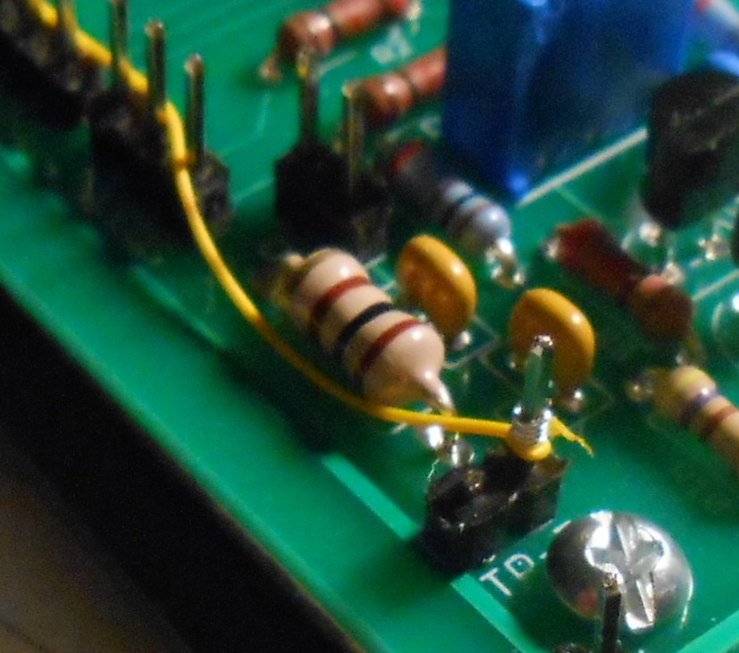
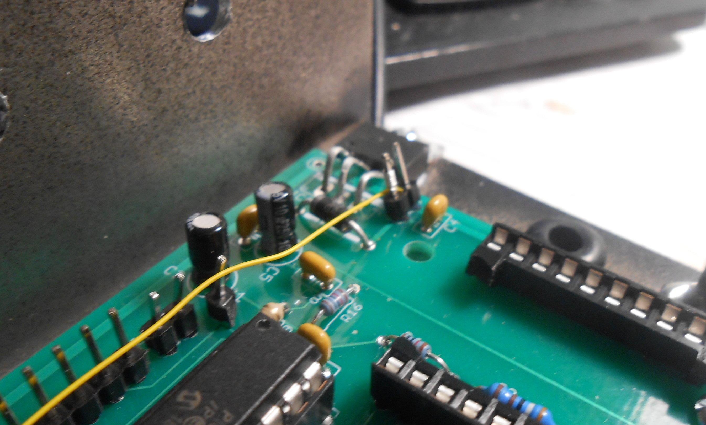
Steps Unique to a TR-5 / TR-7 Installation:
- Sever Pin 2 (the ground pin) on the DDS VFO Board TR-7 pins as it will not be used and could short out the 13
VDC supply from the TR-7. Ensure that you have the correct pin - see picture
- Carefully drill a small hole holes in the rear of the enclosure and place a grommet on it. Fish the previously constructed TR-5 / TR-7 cable
thru this grommeted hole.
- Connect JP-1, pin 1 - (13VDC DDS VFO board input) to TR-7, pin
1 (connection made on the same board) and to ONE terminal of the Biden switch (powers the DDS VFO & disables the
TR-5 / TR-7 intrenal PTO). Note: You may want to jumper JP-1, pin 1 and TR7, pin 1 together first. There was no easy way to make a trace on the PBC for this without enlarging the board.
- Connect the Plug's ENABLE lead (Plug P-308 jumpered pins 7, 8) to the SAME terminal of the Biden switch (see previous step).
- Solder the Biden switch connections
- Connect the Plug's DDS VFO PWR wire (Plug P-308 pin 3) to the OTHER terminal of the Biden switch.
- Solder the Biden switch connection
- Connect the
chassis BACKUP GROUND ground lead to the ground connection lug
to which the ground leads for the TOGGLE, SPLIT, and FAST push buttons have been previously connected.
- Connect the chassis SIGNAL GROUND to the same connection point.
- Connect the PCB FREQ OUT terminals (coax shield connected to the center terminal and the conductor to the outer one). to Plug P-308 Pin 2 VFO IN .
- Steps For Other Installations - Like Ten-Tec, etc.
- Mount
a suitable female power connector for the 13 VDC needed to run the DDS
VFO and connect it to the DDS VFO board power input points
- Mount another jack for the DDS VFO output.
- Mount a third jack for the DDS Transmit lead.
d) How It Works
When the TR-5 or TR-7 is powered on,
the DDS-VFO does nothing. The radio's internal PTO
will tune
the radio. However, then the VFO switch is activated, the DDS VFO
mimics the operation of the stock RV-7 VFO, viz: 13VDC is
sent (through the inductor L5) to disable the radio's internal PTO, to
power the DDS VFO and to 'tell' the radio that the DDS VFO will be used
for both transmitting and receiving.
Note: Please double check your connections before trying to use the DDS VFO.
Caution:
When using the External DDS VFO with a Drake TR 5 / 7, make the
power
and RF output connections BEFORE turning the radio on. If you
attempt a power on installation and accidentally ground the power lead
coming from the RV7 connectior, you may either burn out the L5 100 mh
inductor on the PCB or blow the 5 amp fuse in the TR 5/7 - or both. Replacing the fuse is a PITA.
e) Setting the DDS VFO Output Level - It's important to set the output level of the DDS VFO to match that of the internal PTO.
To
easily accomplish this, place either a scope probe or another high
impedance measuring decice on the Drake TR-7 mother board as shown in
this picture.
With the DDS VFO turned off, measure the voltage at this point.
It should be very close to 1 VAC point-to-point. Then, turn the
DDS VFO on and note the reading. Simply adjust the DDS VFO R18
control until these two measurements are very close, you can easily
switch back and forth. Here are pictures of the enclosed DDS for the TR-5 / 7 - front, back.
f) Birdies and Spectral Purity
Here's how the testing was done. The TR-7 was connected to a
dummy load and the DDS VFO (in a sealed enclosure) was powered by the TR-7's RV7 jack.
Frequency
scans were
done from 1.8 Mhz. meters to 29.7 Mhz with both the TR-7's PTO and with
the DDS VFO for comparison purposes.
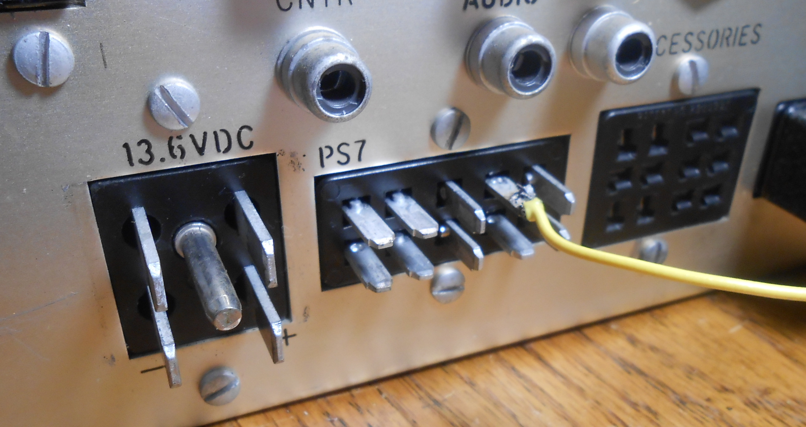
g) Operating SPLIT with the TR-5 / TR-7 and / or Using the RIT Function While Transmitting
To
operate in the SPLIT mode (say, using VFO A for receive, and VFO B for
transmitting), you have to 'tell' the DDS VFO when you are transmitting
both for the SPLIT function to work and for the RIT (if activated) to disengage. The simplest way to accomplish this switching so to connect the
DDS VFO's TMT lead to the matching power supply's (PS-7) VOX relay jack, et voila!
If you are not using the PS-7 with your
TR-7, you have several options to access the DDS VFO TMT lead:
- Drill a small hole in the rear of the TR-7's back panel and
install a female RCA connector whose center conductor will be
connected to pin 8 of the TR-7's rear mounted 10 pin socket, or..
- Simply solder a wire in pin 8, (as I did), or..
- Purchase a suitable plug to fit the TR-7 10 pin soclet and
connect the transmit lead from the VFO to it, or..
- Use the TR-7's 10 volt transmit lead (pin #1 of the
Accessory Connector) and use that signal to switch a 2N3904 (or
equivalent NPN transistor) to ground the DDS VFO's TMT lead (not recommended)
6.
Interfacing Ten-Tec Radios
You
may refer to the following website articles describing how to connect a
DDS VFO within the following radios. Although the initial DDS VFO
used an earlier processor, the conversion and connection sequences are similar:
Note: Connect the DDS VFO transmit lead to the proper point
withing the radio so that the SPLIT function works properly and RIT functionality is disabled in the simplex transmit mode.
Before
populating your board determine where you will mount it. Use
it as a mounting hole drill template. The board can
be
mounted within the radio itself or in a separate, stand alone enclosure.
The DDS VFO will work well in either situation. I've done it both
ways with another PCB and earlier processor version, as noted on
my
website, viz:
a) Radio
Connections - see
picture
- The
DDS VFO needs a source of 13 VCD. For Ten-Tec
radios, this can be secured from a rear mounted phono jack, the
- DDS VFO's output is connected to the VFO input on the
radio's rear panel by removing the factory 'jumper', and the
- Transmit
input is connected to a lead within the radio which provides ground when
the radio is transmitting.
- For Ten-Tec radios,
this is the 'R' lead on the Control Board (on the top side of the radio
just under the optional filter board). This lead can be brought out by
'sparing' up one of the unused phono connectors on the rear
panel. For my OMNI conversion, I used the EXT/TR
jack (after
first removing and insulating
the attached wire).
b) Setting the VFO Output Level
The DDS
VFO output level should be set as close to the output of the
Omni's PTO as possible as the Omni's circuitry was designed around this
value. Setting
the DDS VFO's output higher than this may
generate some 'birdies' and needlessly increase the receiver's
background noise level.
The Ten-Tec's PTO's
output is between .5
Volt to .75 volt,
peak to peak, and you must match this output level with the DDS VFO
unless you want to realign your Ten-Tec Omni, Corsair, etc. A
resistor trimmer (R18) has been
provided for this purpose.
If you have a 'scope,
you
may use it to set the DDS VFO's board right on the money, ensuring that
you are measuring the DDS VFO's output over the coacial cable
connection where it enters the radio. If
you don't have a 'scope,
just turn R18 slowly until the radio begins to
receive AND
transmit
SSB
properly
on all
bands, but no higher.
c)
Birdies and
Spectral Purity - Ten-Tec
Omni D, Series B - DDS VFO installed in an EXTERNAL
enclosure
The OMNI was connected to a
dummy load and the DDS VFO (in a sealed enclosure) was powered by the
OMNI's 12VDC phono jack.. The DDS VFO was connected by a 3 foot length
of coax to the rear of the OMNI (VFO IN Jack).
Frequency
scans were
done from 1.8 Mhz. meters to 29.7 Mhz with both the OMNI's PTO and with
the DDS VFO for comparison purposes.
As shown below, the UNMODIFIED OMNI generates several internal birdies on its own.
These
internally generated birdies are shown in black, while the additional
birdies attributable to the new DDS VFO are shown in red. Those birdies
that can be heard with an antenna connected, with the preselector
properly tuned, and which could possibly
interfere with a weak signal are shown in bold type.
- 160
Meters - 1800,
2000, 1950 - (all present in the PTO
equipped Omni. The birdie at 1950 khz can
be
minimized <but
not
eliminated>
by adjusting R23 -
see the service manual).
- 80
Meters - 3999 - (present in the PTO equipped
Omni)
- 40
Meters - 7,000,
7200 - (both present in the PTO equipped Omni)
- 30
Meters - none present.
- 20
Meters - 14091,
14170 - (both present
in the PTO equipped Omni) ------------ additionally
- with the DDS VFO - 14154, 14272
- 15
Meters -
21320 (present in the PTO equipped Omni)
- 10
Meters (A) -
none present.
- 10
Meters (B) -
28800, 28914 (both present in the PTO
equipped Omni). A
loud birdie at 28978 a well known
Omni design issue.
To
tune this frequency, set
the bandswitch to the 29 Mhz position and tune downward. Check the
service manual for more information.
Note:
One way to cut down on spurious mixing products is to follow the
instructions in the service manual to adjust both R23 and R2 on the oscillator / mixer board. Perform
the adjustments shown in Step 3 and in Step 7 (Mixer Balance).
- 10
Meters (C) - none present.
- 10
Meters (D) - none
present.
Also Note: If
left powered on while an external DDS VFO is connected, the OMNI's PTO
is constantly running and can produce an infrequent birdie on the
upper frequencies. If you want to retain the internal PTO,
simply
move the OMNI's PTO tuning dial should one be encountered.
Alternatively, the power lead to the PTO can be clipped.
Spectral Purity:
The RF output from the Ten-Tec OMNI using either the internal PTO or
the external, enclosed DDS VFO were comparable when viewed on
a
TINY_SA (Tiny Spectrum Analyzer)
7. Heathkit SB-104 - SB104A - See Picture
Interfacing
the DDS VFO with the Heathkit SB-104 / SB-104A is very similar to the Ten-Tec radios, preferably housing it in a
separate enclosure (but it could be mounted within the radio
itself, if desired).
Steps:
- assemble the DDS VFO in a separate enclosure as described here. On the rear of the DDS VFO cabinet, provide:
- an RCA jack for the DDS VFO RF output, a
- suitable BNC connector for the 13VDC power from the radio, and
- another RCA jack for the transmit signal from the SB-104 - 104A.
- temporarily leave the cover off as the VFO level output will have to be adjusted later'
- before
removing the coax VFO jumper on the rear panel of the SB-104(A), remove the
bottom cover, turn the radio on and then measure the level of the VFO
signal (at either the VFO IN or VFO jacks - they are connected
together with a coaxial cable jumper). Make a note of this level as the DDS VFO's output needs to be set to the same level later.
- 2. unplug
and remove this coax jumper. Save it in the event that you ever
want to re-sell the radio in the 'stock' configuration.
- 3. there
are 2 SPARE female RCA jacks on the bottom of the rear panel.
Remove one of them and replace it with a BNC connector.
This will become the 13VDC power source for the DDS VFO. Label this DDS VFO POWER.
- 4. referencing the SB-104(A) schematic,
locate accessory plug CY on the rear panel. This plug is
used to power the stock SB-104 external VFO. It also provides
contacts for an external linear amplifier.
- 5. Using your meter, verify that pins 2 and 5 of the plug are jumpered together externally, as they should be.
- 6. on the CY accessory plug socket, ground pin 9
(a violet colored wire) - this will serve to indicate a transmit
indication to the DDS VFO when the SB-104(A) is in the transmit mode.
It can simply be connected to pin 6 of the same socket which is
already grounded - USE YOUR METER TO VERIFY THIS.
- 7. on the CY accessory plug socket, connect pin 8
(a yellow colored wire) to the center condoctor of the existing spare
RCA jack on the rear of the SB-104(A) rear panel. This will be
the transmit indicator to the DDS VFO. Grounding this lead is required
whenever the SPLIT or RIT controls are used during transmitting. Label this DDS VFO TRANSMIT.
- 8. on the CY accessory plug socket
there's a source of 13 VDC from the radio's power supply. With
your meter and with the radio powered on, verify that 13VDC is
present on pin 11 (red wire).
- 9. turn the radio off and unplug the power supply.
- 10. connect CY accessory plug socket pin 11 - thru an inline 1 amp fuse - to the center of the BNC connector just installed in place of the other spare female RCA jacks.
- Note: The fuse is a safeguard as -without it - any inadvertent ground within the DDS VFO or on the power feed itself could cause a real mess.
In-line fuse holders are readily available on ebay, Mouser or auto
supply houses. With an in-line fuse holder there's no need to
drill another hole in the rear panel.
- 11. prepare a 2 wire power cord (lenght to suit) consisting of 2 BNC plugs - one at either end. Use your meter to verity proper polarity and continuity.
- 12. prepare an RG-174 coaxial jumper cable (length to suit) with male plugs at eaither end - verify continuity.
- 13. connect the power jumper between the SB-104(A) and the DDS VFO.
- 14. connect the TRANSMIT jumper between the SB-104(A) and the DDS VFO.
- 15.
connect the double ended male coaxial cable you just prepared between
the DDS VFO's output and the SB-104(A)'s VFO in jack
- 16. activate SB-104(A) power and veirfy that the DDS VFO VFOA lamp lights up.
- 17. The DDS
VFO output level should be set as close to the (previously measured) output of the SB-104(A)'s as possible as the radio's circuitry was designed around this
value. Setting
the DDS VFO's output higher than this may
generate some 'birdies' and needlessly increase the receiver's
background noise level. A
resistor trimmer (R18) has been
provided for this purpose.
- 18. Test the new DDS VFO working with the SB-104(A). For
the transmit to work properly, you'll need to place the radio in the
high power mode or the Radio will not operate on transmit.
- 19. Enjoy the new RIT and FAST tune capabilities as well as dual, drift-free digital VFOs
8. Replacing the SB-104 (A) Burroughs Digital Display with a Newer, State-of-the Art Unit
Note: I'm just posting some suggestions that may be of interest
to anyone contemplating the conversion. No mention is made here
about the physical conventions of mounting the display within the
radio, although it could be mounted in a separete enclosure, if desired.
As shown on the SB-104(A) schematic,
the PREMIX signal consiste of the Heterodyne Oscillator frequency less
that of the VFO's frequency. This premixed signal is sent over to
the SB-104 A's Frequency Display Circuit Board on coaxial lead J-101.
With this 1970's counter logic, the BFO frequency is not
actually measured, but assumed. The switched leads on pins 22, 23
and 24 mimmic the value of the BFO to be subtracted when +5 VDC is
applied to the proper lead for the selected mode. The service
manual describes this process in excruciating detail.
Now, the Chinese 6 Digit frequency counter (available on eBay) has
provisions for two separate frequency offsets.
One is active with pin 4 on the rear of the unit ungrounded, and
the second becomes active when pin 4 on the rear of the unit is
grounded (to pin 3),. On the rear of the unit there is a row of 8
sequential pins, Pin 1 is the one right by the triangle, pin 2
is above it, pin 3, then pin 4, etc. One offset is active when
pins 3 (ground potential) and 4 are open, the other is active when they
are shorted together, or when pin 4 is simply grounded. It's that
simple.
Now, according to the pictures in the assembly manual, the mode
selection switches work in a mutually exclusive mode - that is -
pressing one down releases the others. Furthermore, there appear
to be spare onntacts on each of the switches so one would not need to
disturb the existing wiring.
So......the first step would be using a frequency counter to measure the actual frequency of the LSB and USB oscillators on the Carrier Generator Circuit Board and write each of them down (CW will not be needed as the USB oscillator will be used when receiving CW).
Next, program the respective offsets into the Chinese 6 Digit Frequency counter for the USB/CW and LSB modes. Ground pin 4 when entering the LSB offset.
Then, wire up the spare contacts on the mode switches so that the LSB button grounds the LSB offset and is open for the USB offset.
Finally, connect the input of the 6 LED Chinese Frequency
Counter to the SB-104 (A)'s PREMIX signal. Use a small value
capacitor so this connection doesn't load down the circuit.
Once this has been proven to be working satisfactorily you might
consider removing the display board and that annoying DC / DC converter.
Also Note:
This technique would most probably work with the HW-104, although
it would probably be prudent to wire it up in a separate enclosure,
providing, power and mode selection leads from the radio along with the
PREMIX signal.
dit...dit
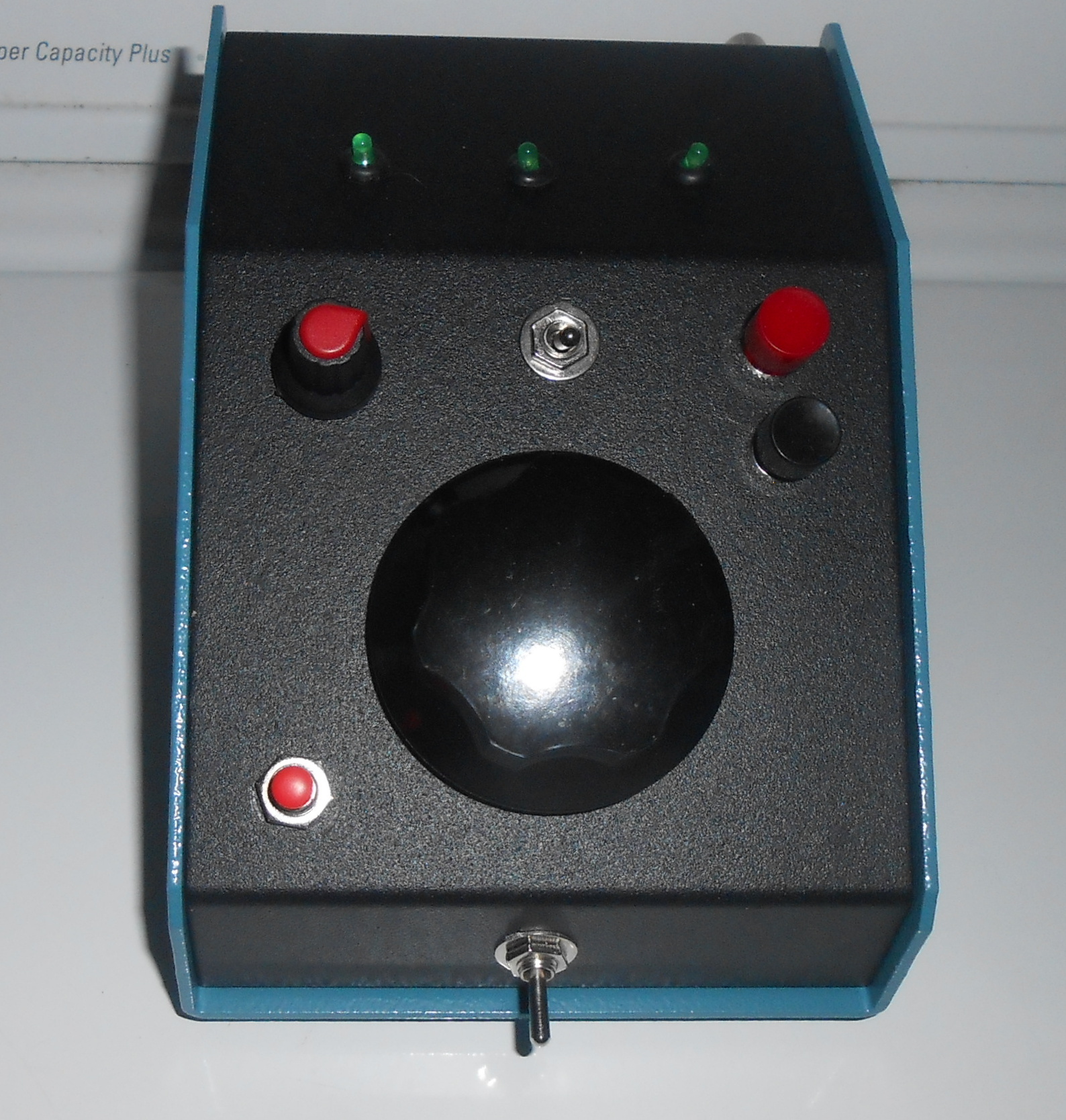
9. DDS VFO Commands and Controls
There are 3 working buttons, one tuning
knob, two switches and a smaller knob (RIT) on the front of this box, the:
- the Black Button
is the VFO
TOGGLE.
Tapping it will switch the VFO's. This
way, VFO A
can be set to one frequency while VFO B set to another, handy for SPLIT
operation.
Note:
Holding the
VFO
Toggle Button down for about one second will
LOCK the encoder. The three LED's will light to indicate the
LOCKED
status.
While
locked, the radio will still transmit based upon the previous settings
and the RIT will continue to function unless the radio had been in the SPLIT mode before being locked. Tapping
the
VFO
Toggle Button will restore tuning.
- the Red Button
activates the SPLIT
function. When pushed again, the active VFO's frequency will
be set in the standby VFO. The VFO's
will not be switched.
- to STORE
the last used frequency so that it will be retrieved when the DDS
VFO / radio combination is powered up again, first depress and hold the
FAST
button. While keeping the FAST
button depressed, tap the SPLIT
button (the VFO will not go onto the
SPLIT mode), and all 3 LED's will light. Then, release the FAST
button, the LEDs will blink, and the data will be written.
When
powered up again, the DDS VFO will revert to the last used VFO and VFO
frequency. If the SPLIT
function was in use, it - too - will be restored.
Important Note: FREQUENCY STORE
capability is optional.
To enable it, ground the FLASH pin on the DDS
VFO PCB. If not grounded, upon power up the frequencies
will be set to 5.5
Mhz for
VFOA, and 5.0 Mhz for
VFOB
- this switch activates the RIT
control shifting the frequency 1.2 Khz in either direction.
Turning the switch off restores the original frequency.
RIT
will not work while in the SPLIT mode.
- Once again,
if you use the RIT function in the transmit simplex mode without the
radio grounding the transmit lead, the RIT setting will influence the
transmitted signal (bad news!). Therefore, it's mandatory to connect the DDS VFO transmit lead to the appropriate connection within your radio.
- the FAST
button (or switch, if desired)- will change
the tuning rate from 10 Hz to 1Khz per step - when continuously
depressed (or operated)
10. Using it On-the Air
Using the DDS VFO controller is simple. For SIMPLEX operation,
there are two VFO's to choose from - VFOA and VFOB.. The only
concern here involves CW operation. Most CW transceivers provide
some kind of a frequency offset (usually 600 to 750 hz) from the
transmit signal. This is done automatically in the TEN-TEC series
and in the Drake TR-7. Because these offsets differ from radio to
radio, it would be difficult (but not impossible) programming the radio
specific offset to be used in the DDS VFO software. Furthermore,
an additional front panel switch would be required to indicate when in
the CW mode.
So, when simplex CW operation is
contemplated, the RIT control can be used to provide this offset, if
desired ----------- or if even needed.
For SPLIT operation, you'll need to set both VFO's to the same frequency by tapping the SPLIT button. Then, use either VFO (say, VFO A) to receive the station who is working in the SPLIT mode. If the station operating SPLIT instructs you to call on a particular frequency, just toggle to VFO B and set the desired frequency in it, and then toggle back to VFO A. When you are all set up, push the SPLIT button and the SPLIT LED will light. So, you'll continue to receive on VFO A, but will be transmitting on VFO B - the VFO lamps will flash accordingly as you transmit.
Another, less publicized benefit of having 2 VFO's is the ability
to keep track of 'conversations' - say, during a contest. If you
come across a desired DX station in QSO with another ham but want to
make another contact in the meantime, simply switch to the other VFO
and tune around. You can always spot check your original 'target'
by just tapping the TOGGLE button - very simple, n'est-ce pas?
11. Drake Service Manuals and Alignment Instructions
Copyright (PCB and Software) 2021, 2022, 2023, 2024 K3JLS